3D Printing Jump Start: complete notes
Everything from the 76-slide deck (slide text, SmartArt, charts, speaker notes, videos) plus the full Simplify3D Print Quality Troubleshooting guide. Tap any picture to enlarge it. Highlighted = numbers and facts likely to be tested.
1. Definition & history
Definition
“The term 3D printing refers to a range of methods in which material is deposited, connected, or solidified under computer control to form a 3D item with material being placed together layer-by-layer, such as polymers, concrete, plastics, liquids, or powder grains.”
Excell J, Nathan S. The rise of additive manufacturing. The Engineer, 2010 (24 May). Slide credit: Dr. Garnet Hertz.
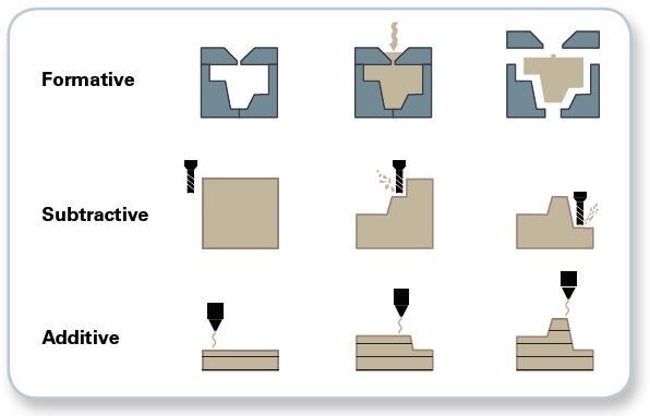
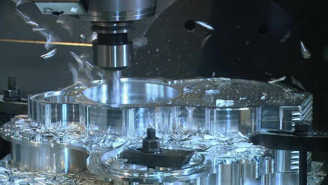
Speaker notes: Additive Manufacturing (3D printing) vs Subtractive Manufacturing (CNC milling). 2009: the FDM (Fused Deposition Modeling) patents expired.
Evolution
Older than the Moon landing (timeline):
| Decade | Development |
|---|---|
| ’50s | Photopolymer resin (DuPont Institute) |
| ’60s | Dual-laser hardening (Battelle Institute) |
| ’70s | Solid Photography (Dynell Electronics) · Photochemical Machining (Formigraphic) |
| ’80s | Single-beam curing (H. Kodama) · Commercial units (3D Systems) · First FDM patent (Stratasys) |
| ’90s | Commercial FDM units (Stratasys) · Powder sintering (DTM, now 3D Systems) |
The early work covers resin, extrusion and metal printers, i.e. almost all 7 recognised 3D printing technologies. Stratasys held a monopoly on FDM through its patent.
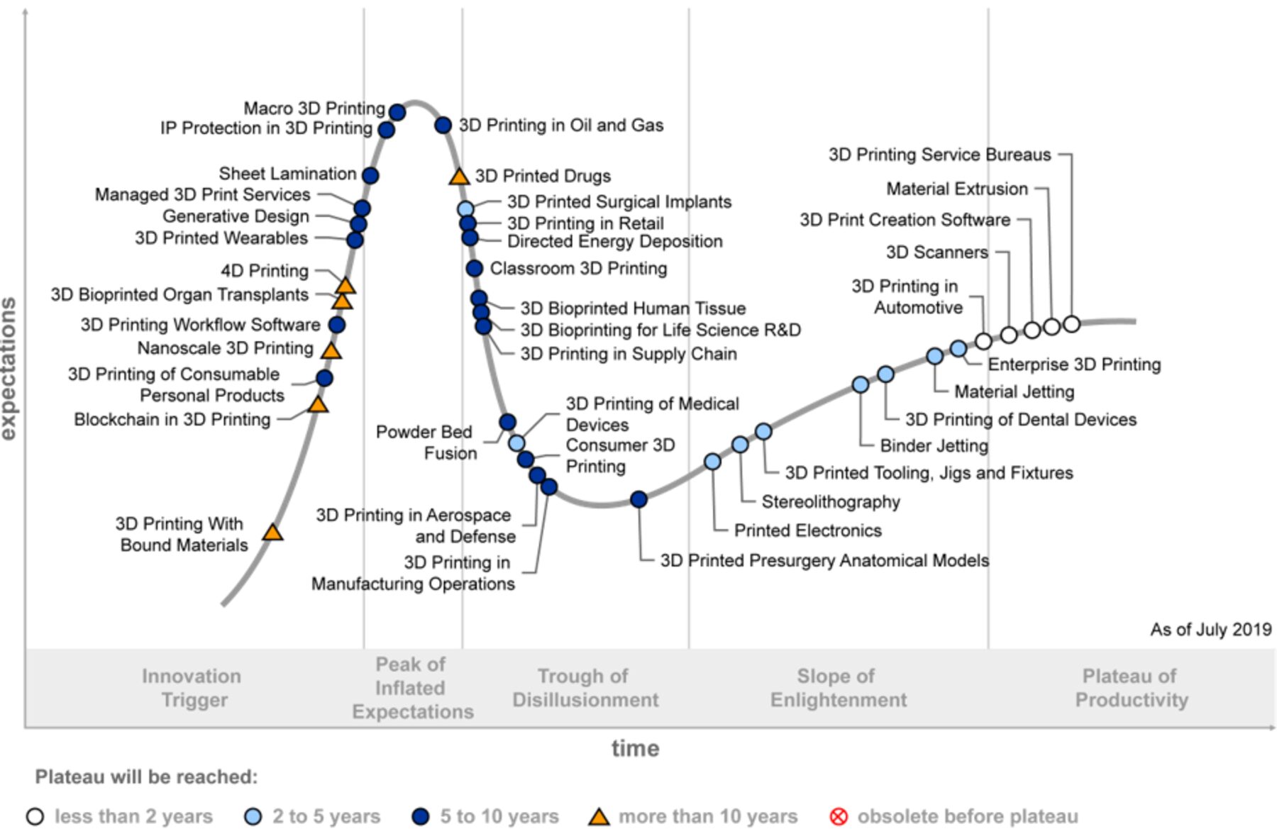
A decade of enthusiasm: followed the lifting of the FDM patent (2009): hobby use, hype, rapid prototyping equipment (linked to the success of extrusion, and more recently also VPP).
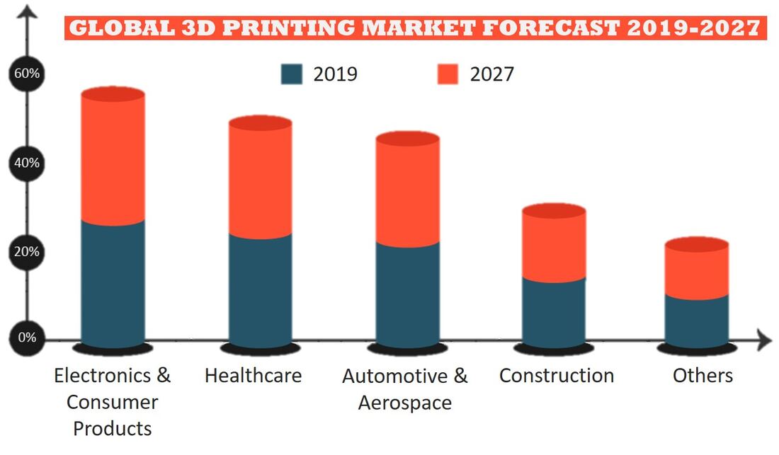
Market: the global market is at over 12 bn USD and expected to double by 2027.
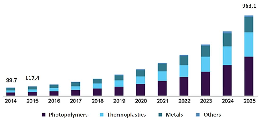
Materials: also booming, reaching 1 bn by 2027 in the US alone, 4 bn globally. The 3 major techniques show up in the material categories: photopolymers, thermoplastics, metals (+ others).
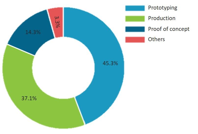
AM in mechatronics: the majority of use is prototyping. Denmark, a country initially reluctant towards AM, is a good example: five years ago only 4% of all companies used AM; the Danish Technological Institute reported over one hundred new cases of helping companies start implementing 3D printing in one year. Until 2018, TMECH and AIM had collected 26 publications related to 3D printing; since then there have been separate AM tracks because of its increased potential.
Sources on the slide: Wohlers Report · Gartner 3D Printing Hype Cycle (2020) · Inkwood Research · Grand View Research · Fortune Business Insights.
2. Advantages
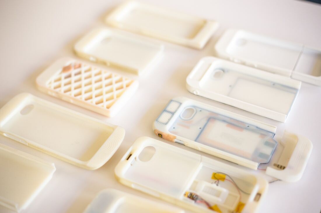
Fast Design Iterations
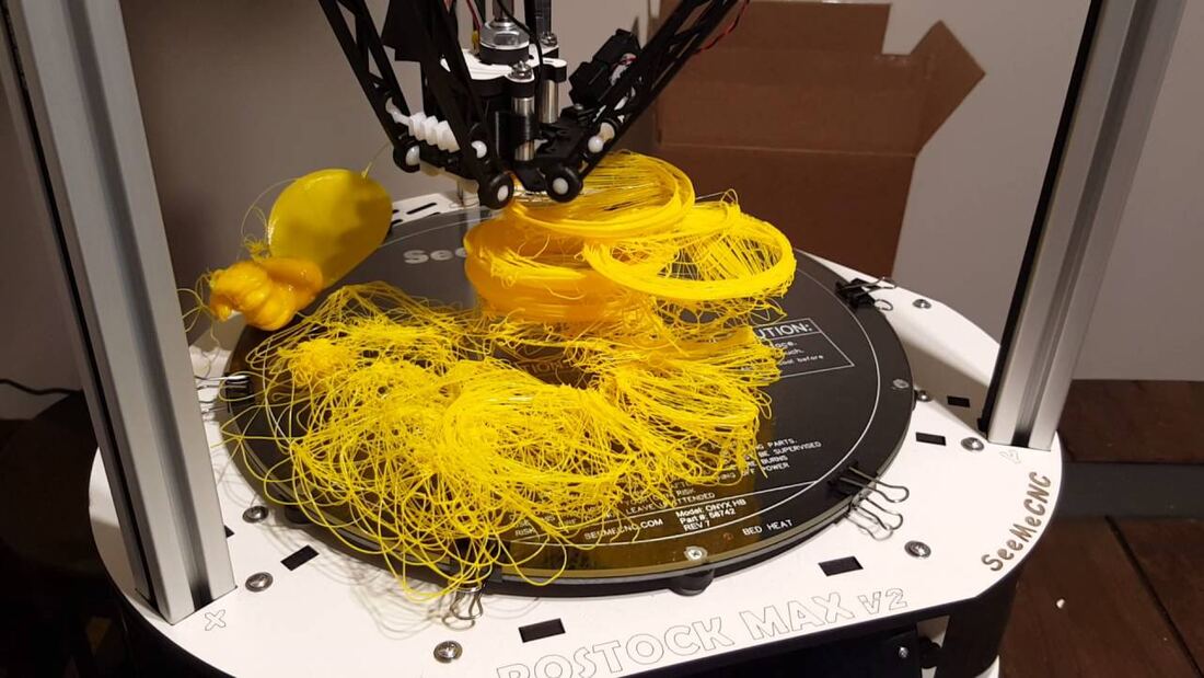
Cheaper Failures
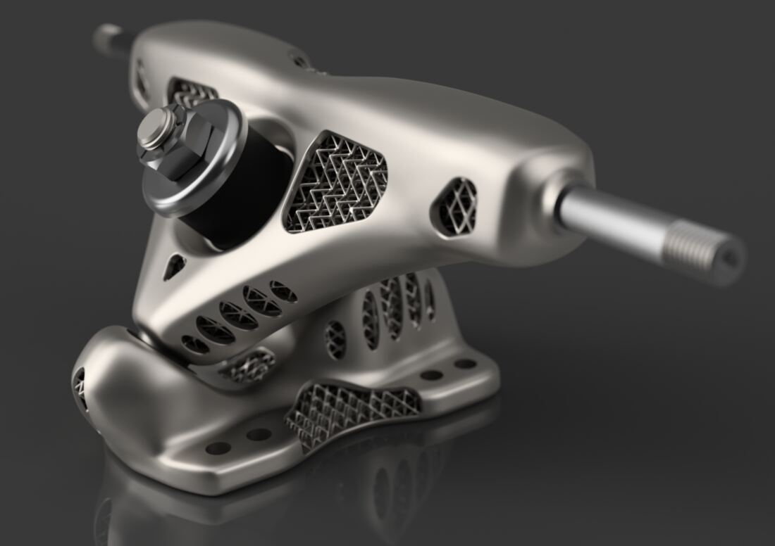
Complex Geometries
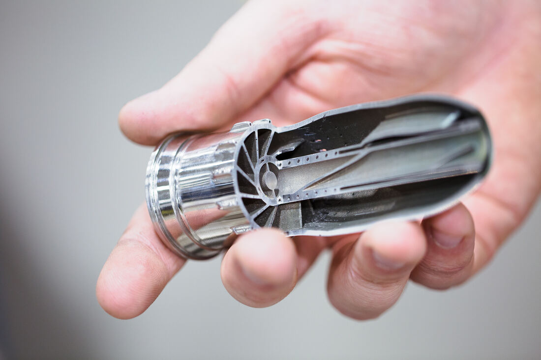
Lighter Stronger Parts
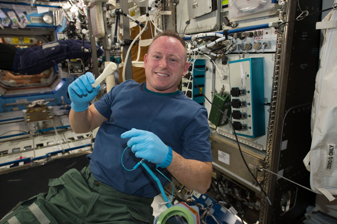
On Demand Manufacturing
Waste Reduction
3. Disadvantages
Resolution & Surface Finish
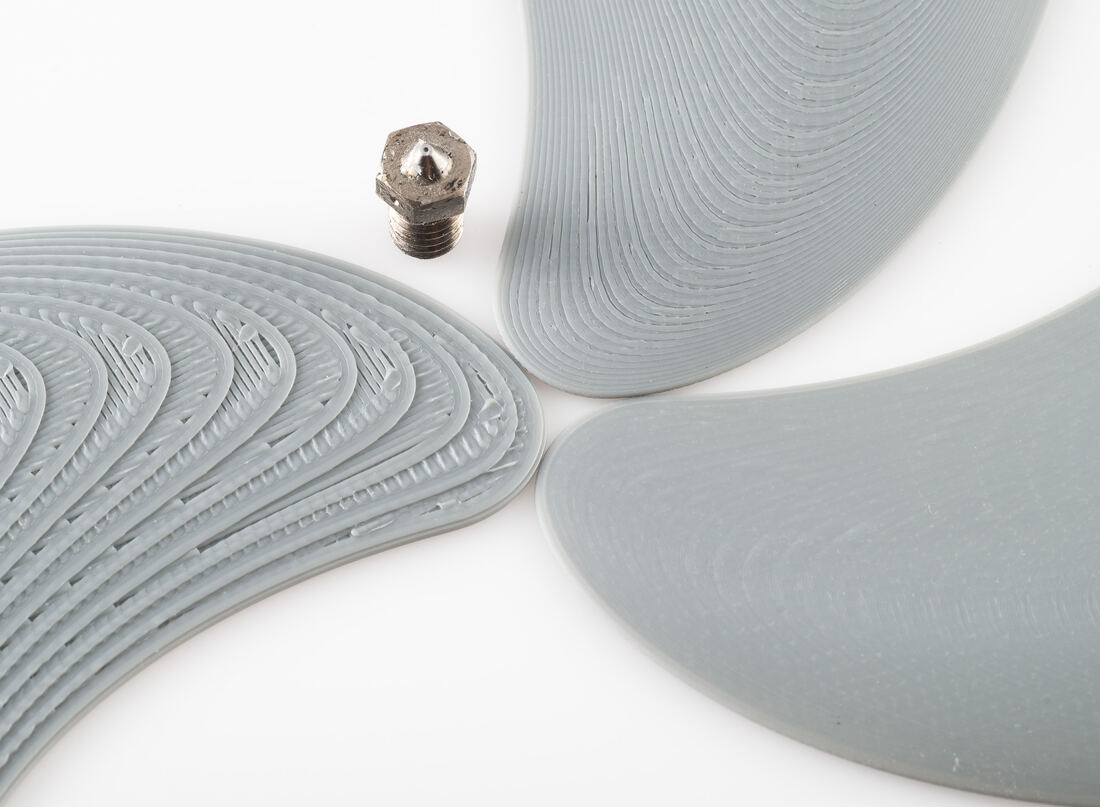
Size Constraints
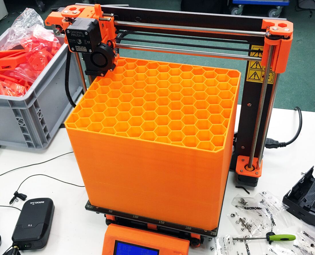
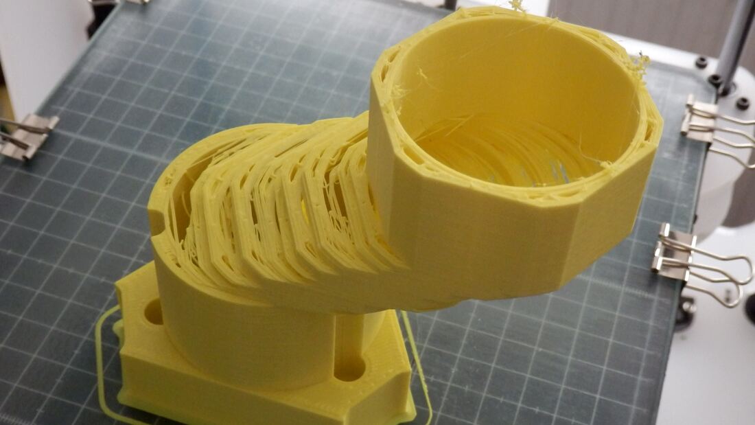
Hardware Reliability
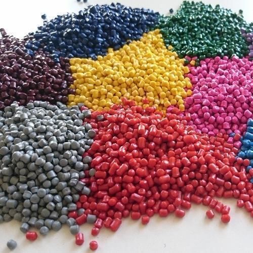
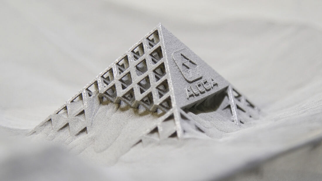
Material Limitations
Printable material is far more expensive than the raw material:
| Material | Printable form | Raw |
|---|---|---|
| ABS | Stratasys 250 €/kg | Raw granulate 1.2 €/kg |
| Aluminium | 72 €/kg | 2.7 €/kg |
| TPU | 32 €/kg | 7 €/kg |
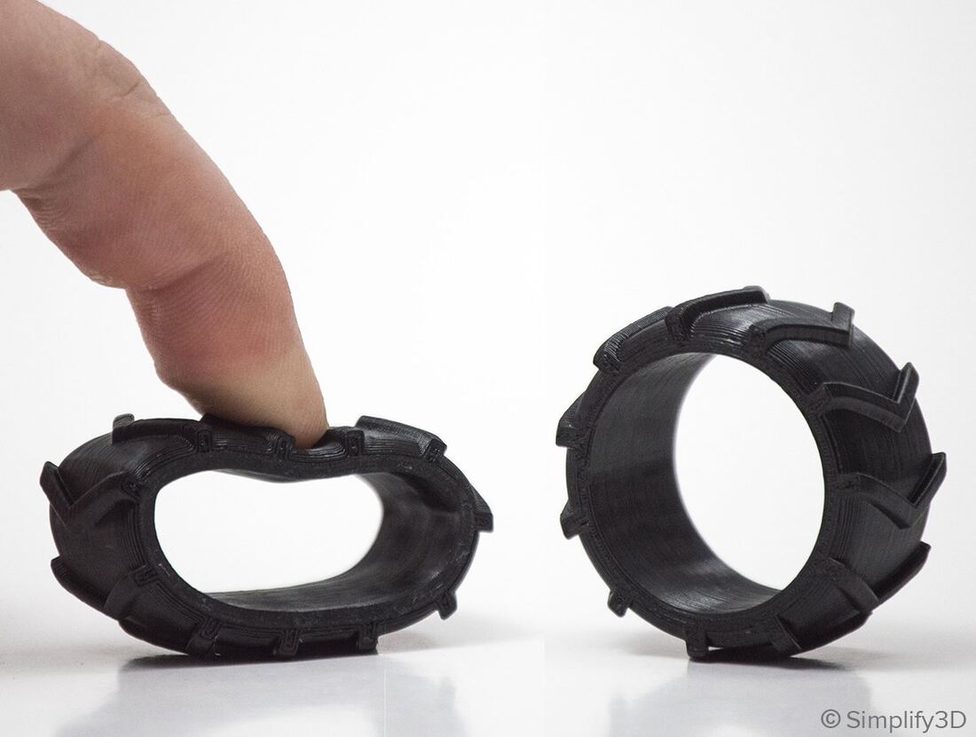
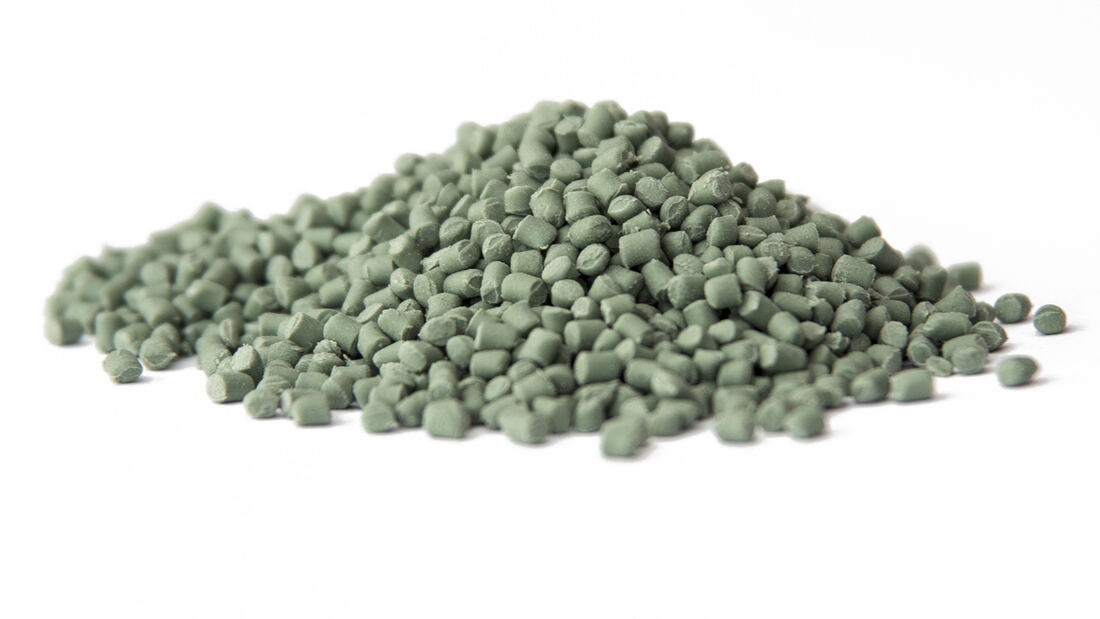
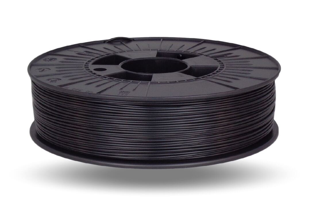
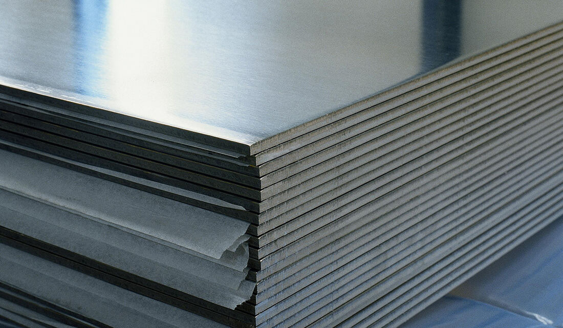
Expensive At Scale
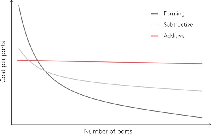
Injection moulding has large initial costs, but is very cheap at scale.
4. 3D print workflow
Model → Slice → Print
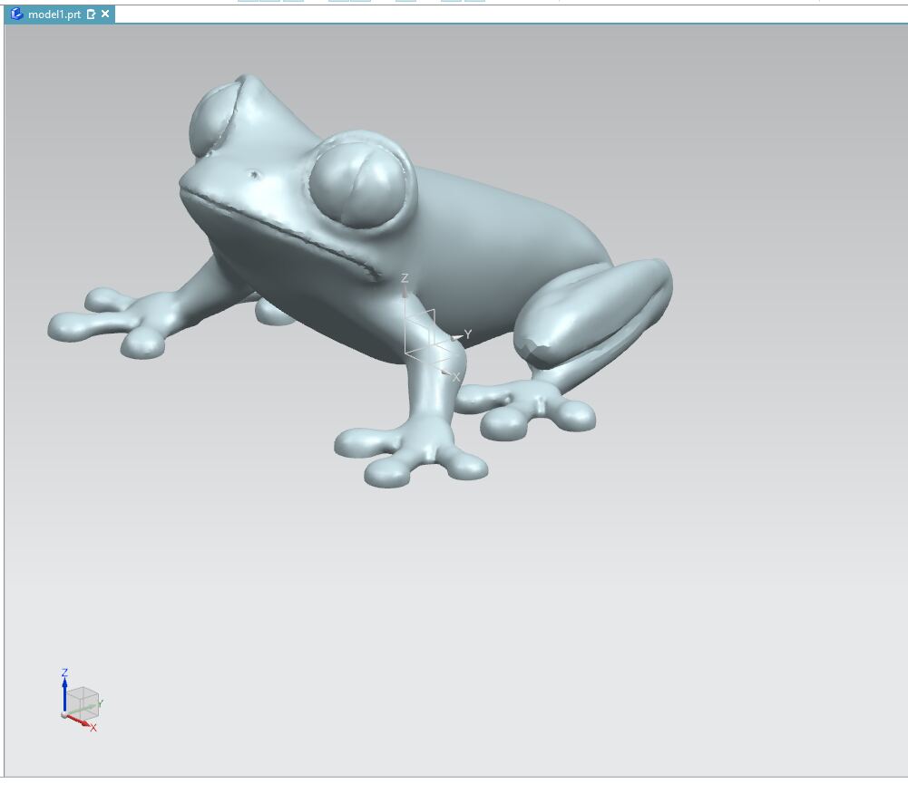
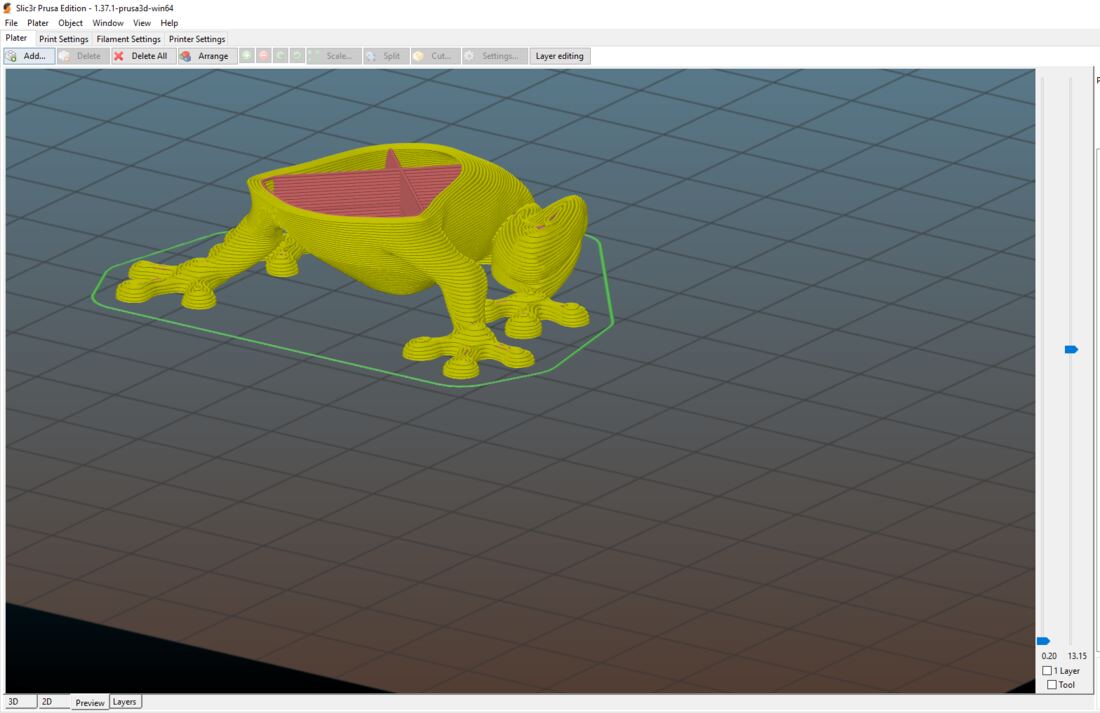
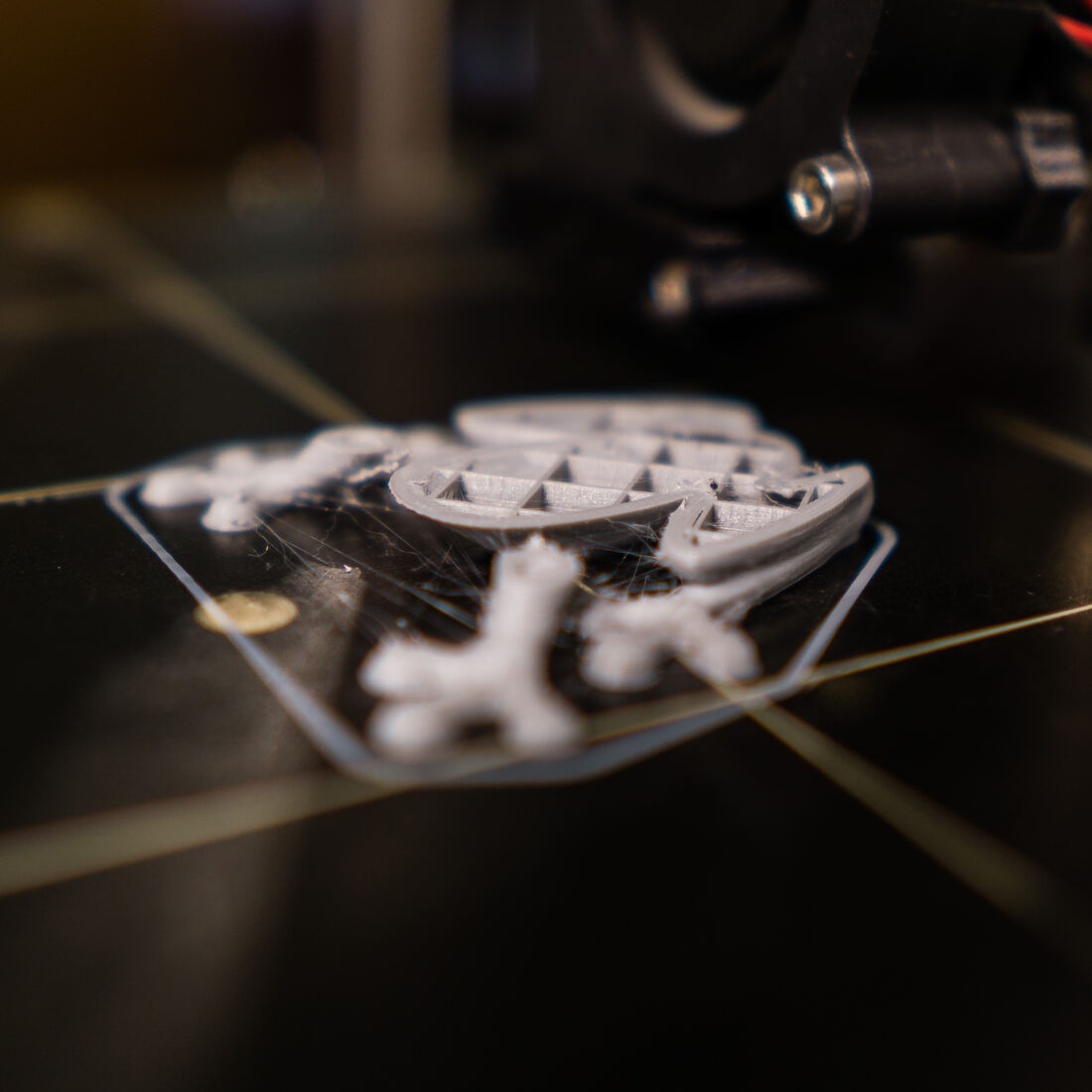
| Model (slide 20) | Slice (slide 27) | Print (slide 37) |
|---|---|---|
| What NOT to print Orient for strength Orient for printing ease → Overhang · Aesthetics · Bridging (slide 23) |
Layer height Infill density Infill patterns Width & perimeters |
Material choice → Requirements · Price · Printing ease (slide 38) Printer technology Printer setup → Clean & prepare · Load material · Calibrate (slide 73) Part removal Post processing |
5. Model
What not to print
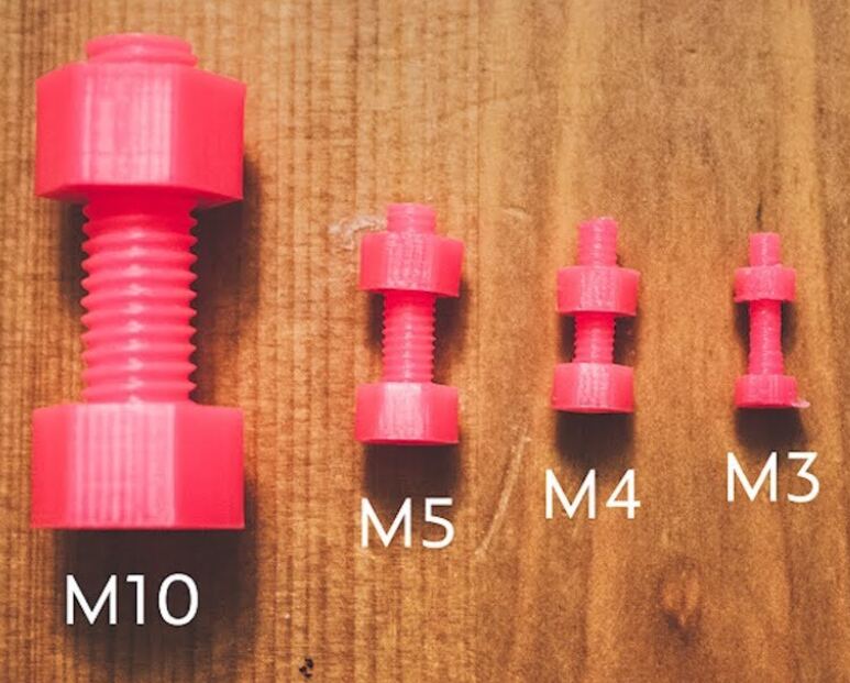
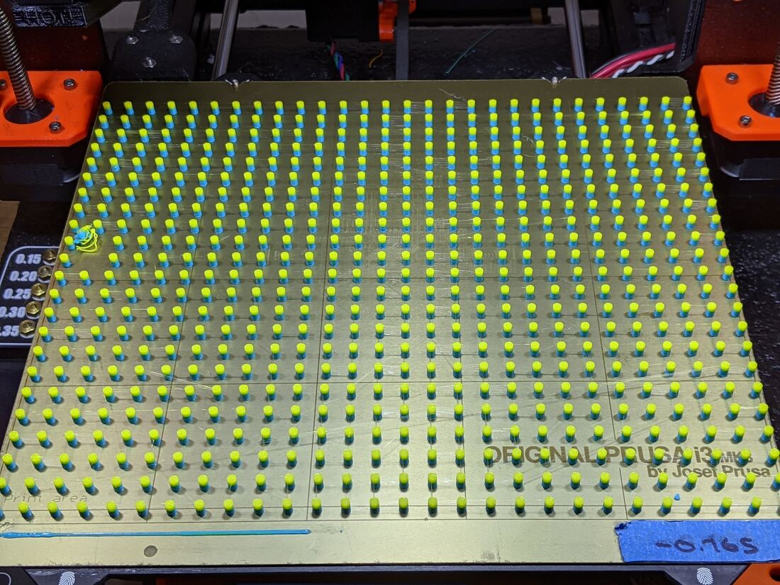
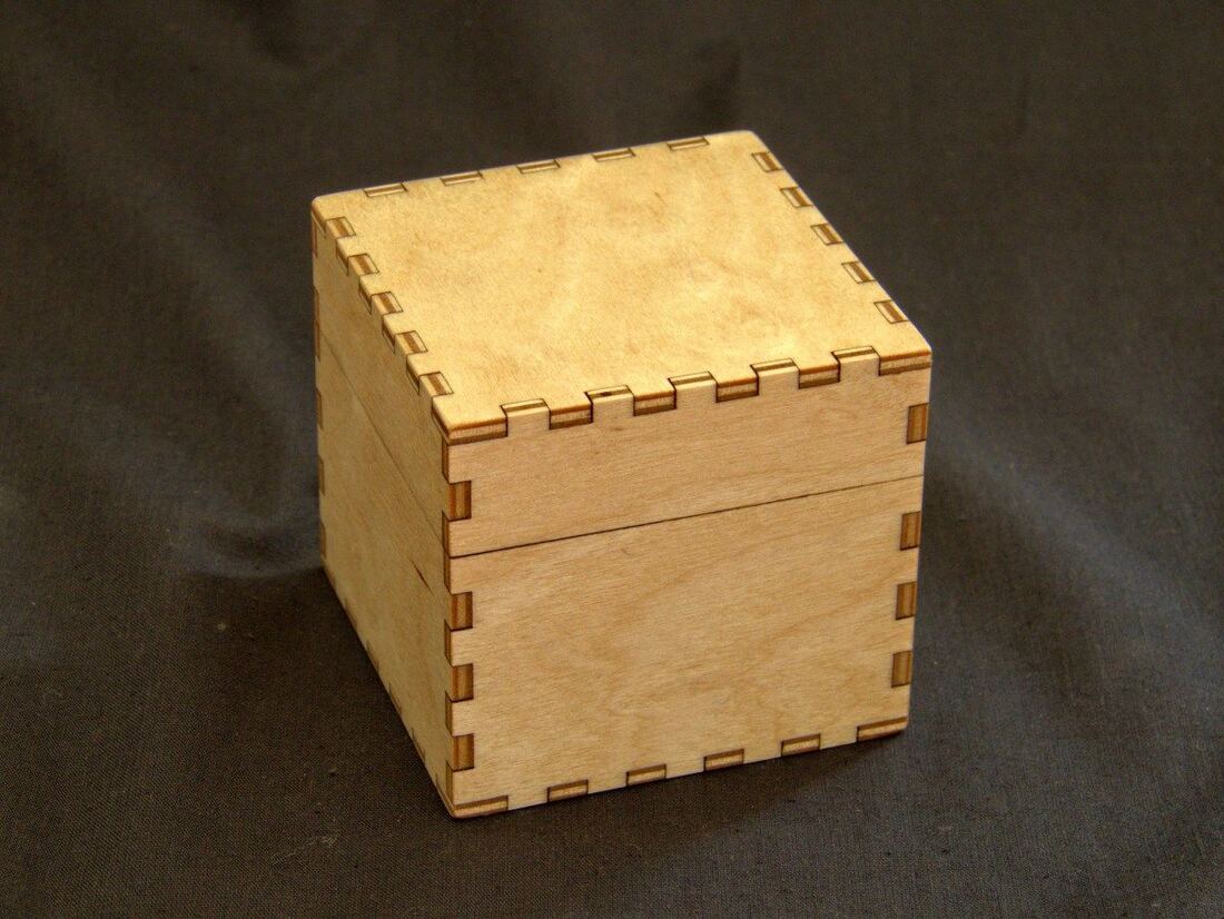
Orient for Strength
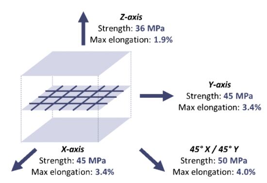
| Direction | Strength | Max elongation |
|---|---|---|
| Z-axis (across layers) | 36 MPa (weakest) | 1.9% |
| X-axis | 45 MPa | 3.4% |
| Y-axis | 45 MPa | 3.4% |
| 45° X / 45° Y | 50 MPa (strongest) | 4.0% |
Why: in Z the load has to go through layer-to-layer bonds. Orient parts so loads run along the layers.
Overhang
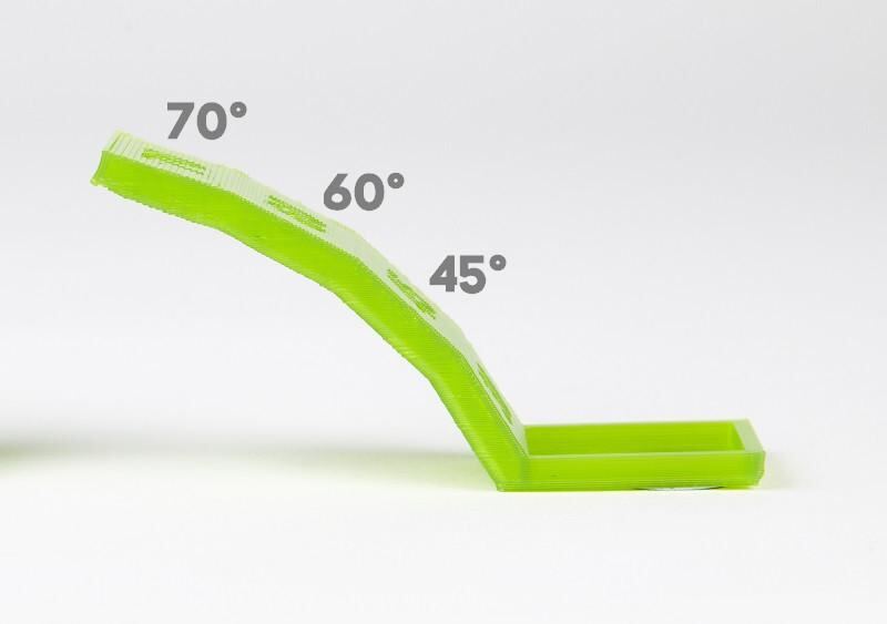
Source: rigid.ink, “how to print overhangs, bridges and exceeding the 45° rule”. Simplify3D adds: at 0.2 mm layers you need support above ~45°; at 0.1 mm layers overhangs can reach ~60° (smaller steps per layer).
Aesthetics
Bridging
6. Slicing
Layer height
Layer height vs strength and time (my3dmatter)
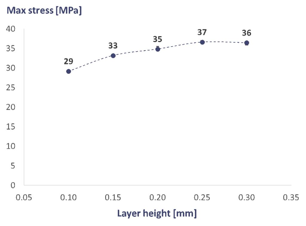
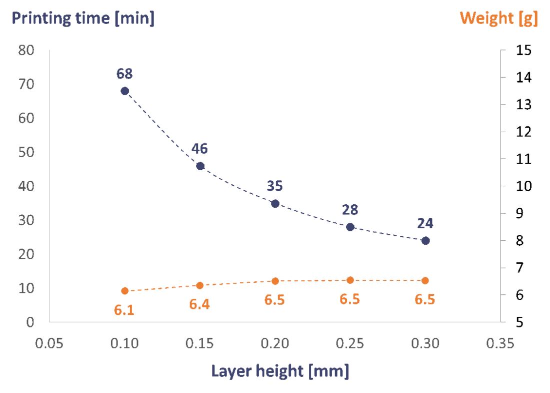
| Layer height (mm) | 0.10 | 0.15 | 0.20 | 0.25 | 0.30 |
|---|---|---|---|---|---|
| Max stress (MPa) | 29 | 33 | 35 | 37 | 36 |
| Print time (min) | 68 | 46 | 35 | 28 | 24 |
| Weight (g) | 6.1 | 6.4 | 6.5 | 6.5 | 6.5 |
Rough layer height = strong parts. Fine layer height = weaker parts. (It's counter-intuitive, which makes it likely exam material.)
Infill Density
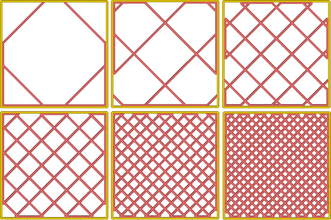
Infill vs strength and time (my3dmatter)
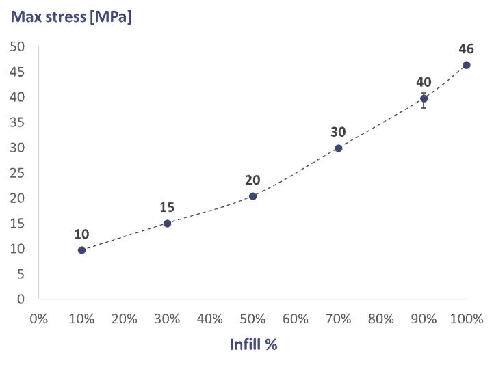
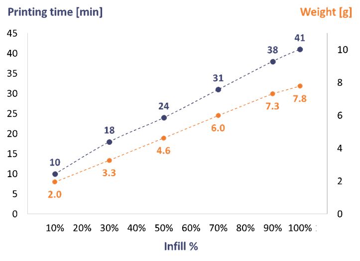
| Infill | 10% | 30% | 50% | 70% | 90% | 100% |
|---|---|---|---|---|---|---|
| Max stress (MPa) | 10 | 15 | 20 | 30 | 40 | 46 |
| Print time (min) | 10 | 18 | 24 | 31 | 38 | 41 |
| Weight (g) | 2.0 | 3.3 | 4.6 | 6.0 | 7.3 | 7.8 |
High infill = strong parts = long print time. Low infill = weaker parts = short print time.
Infill Patterns
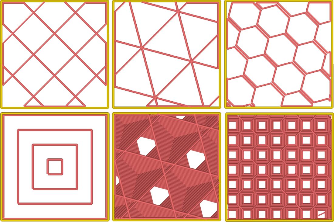
Pattern vs compressive strength (kgf)
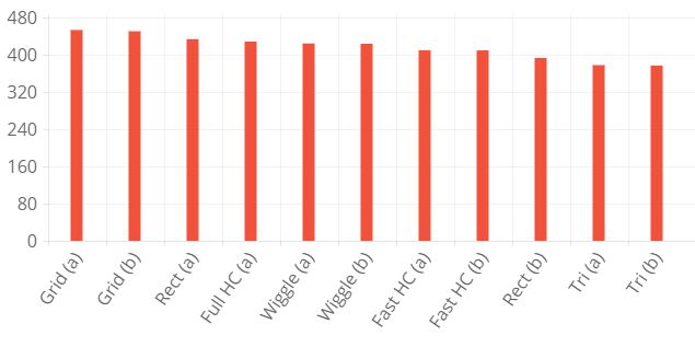
It shows some correlation, but the results are very close. The jury is still out on how pattern affects compressive vs tensile strength.
Patterns on a ring: Concentric · Grid · Hilbert curve
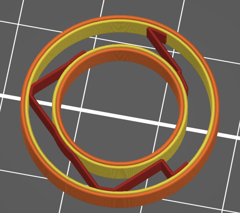
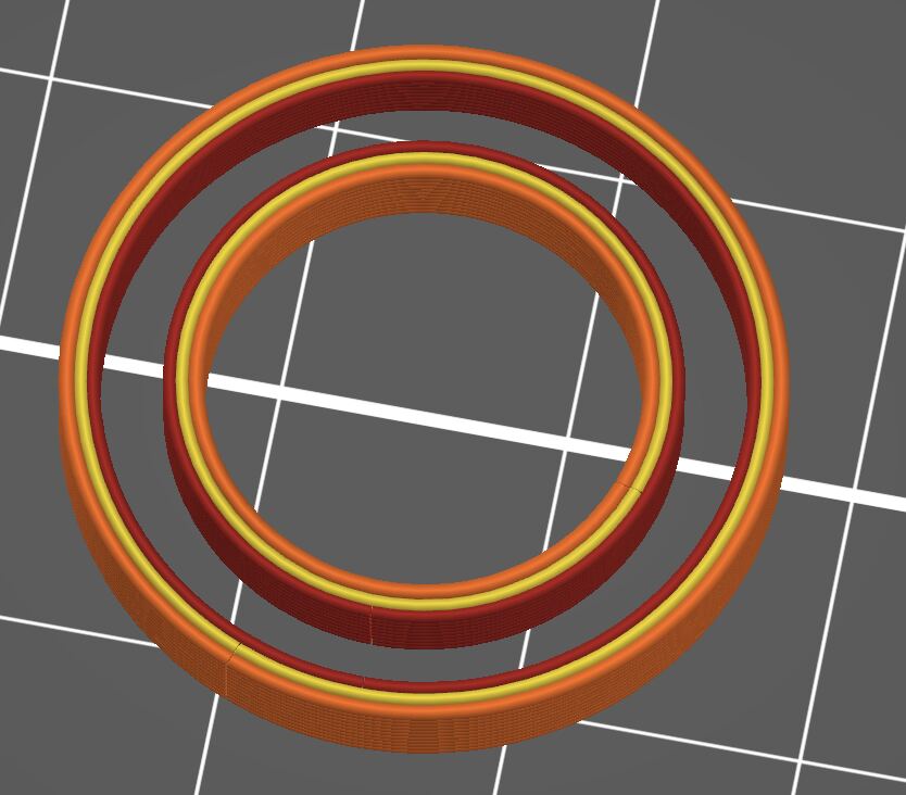
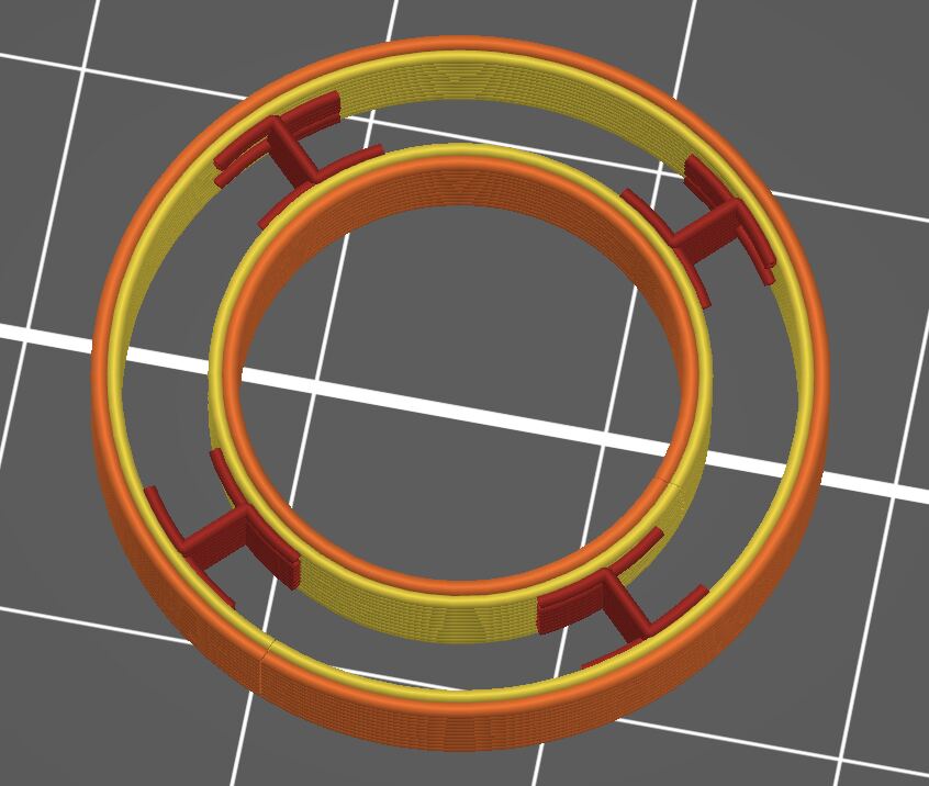
For flexible materials the pattern matters quite a bit, because it decides how the part squishes. Be careful with thin objects and circular objects.
Perimeters & width
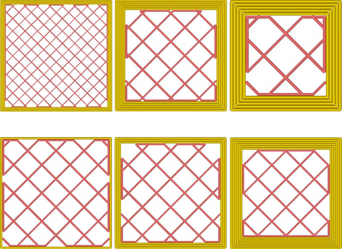
Shells matter (my3dmatter)
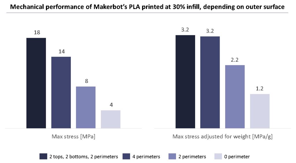
| Configuration | Max stress (MPa) | Stress adjusted for weight (MPa/g) |
|---|---|---|
| 2 tops, 2 bottoms, 2 perimeters | 18 | 3.2 |
| 4 perimeters | 14 | 3.2 |
| 2 perimeters | 8 | 2.2 |
| 0 perimeters | 4 | 1.2 |
Perimeters matter a lot, if not the most.
Extra slicing rules from Simplify3D
- Layer height should be ~20% smaller than the nozzle diameter: 0.4 mm nozzle → max ~0.32 mm.
- Top solid section at least 0.5 mm thick: 0.25 mm layers → 2 top layers; 0.1 mm layers → 5. Extra solid layers go inside the part and don't change its outer size.
- Extrusion width should be 100–150% of the nozzle diameter.
- 30% infill = 30% of the interior is plastic and the rest is air, inside a solid shell.
- Strong infill patterns: Grid, Triangular, Solid Honeycomb. Rectilinear and Fast Honeycomb trade strength for speed.
- Infill extrusion width can be increased (e.g. 200%) for thicker, stronger infill walls. Lines get spaced further apart to keep the same %, so raise the infill % as well.
- Skirt = outline around the part that primes the extruder. Brim = extra rings attached to the part edge (like a hat brim) for more bed contact. Raft = platform printed under the part. Brims and rafts help adhesion and warping.
- Most nozzles are 0.3–0.5 mm (0.4 and 0.5 are popular). Common filament diameters: 1.75 mm and 2.85 mm.
7. Print
8. FDM filaments
PLA: Polylactic acid
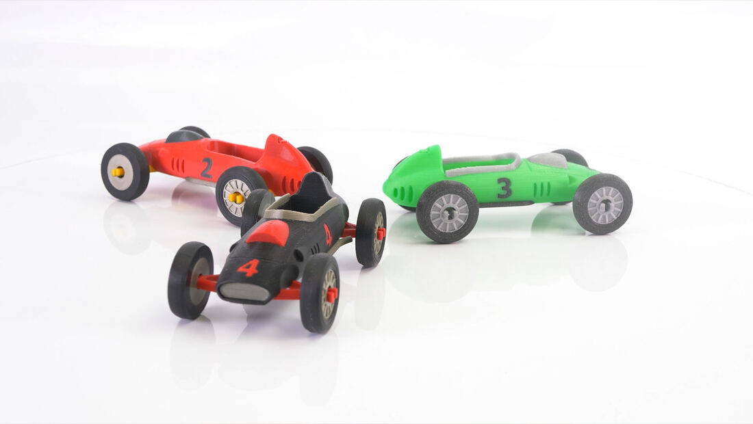
- Prints very well
- Doesn’t smell during print
- Biodegradable
- High strength
- Low flexibility
- Minimal warping
Tg 60 °C · 1.25 g/cm³ · 36–55 MPa · 3.5 GPa · 0.3–0.5% · ~20 €/kg
ABS: Acrylonitrile butadiene styrene
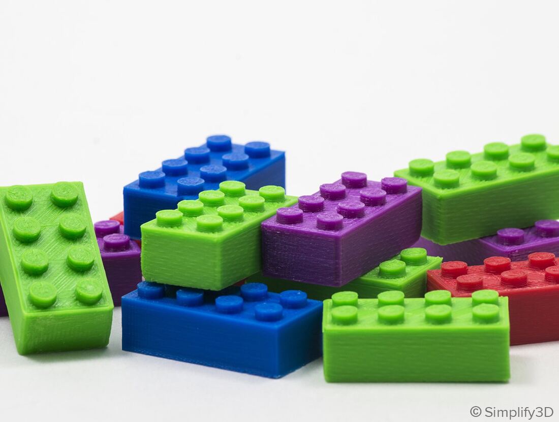
- A little hard to print
- Fumes during print
- Tendency to shrink
- Medium flexibility
- High durability
- Good temperature resistance
Tg 100 °C · 0.9–1.2 g/cm³ · 25–50 MPa · 1.1–2.9 GPa · 0.7–1.6% · ~25 €/kg
PETG: Polyethylene terephthalate glycol
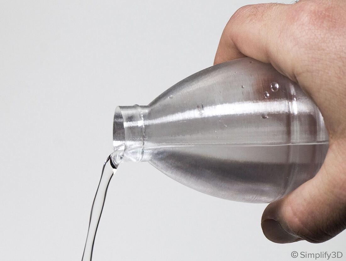
- Middle ground between PLA and ABS
- Easier to print than ABS
- High strength
- Medium flexibility
- High durability
- Absorbs moisture (hygroscopic)
Tg 51–64 °C · 1.28 g/cm³ · 60–66 MPa · 2.1 GPa · 0.2–1% · ~25 €/kg
Nylon
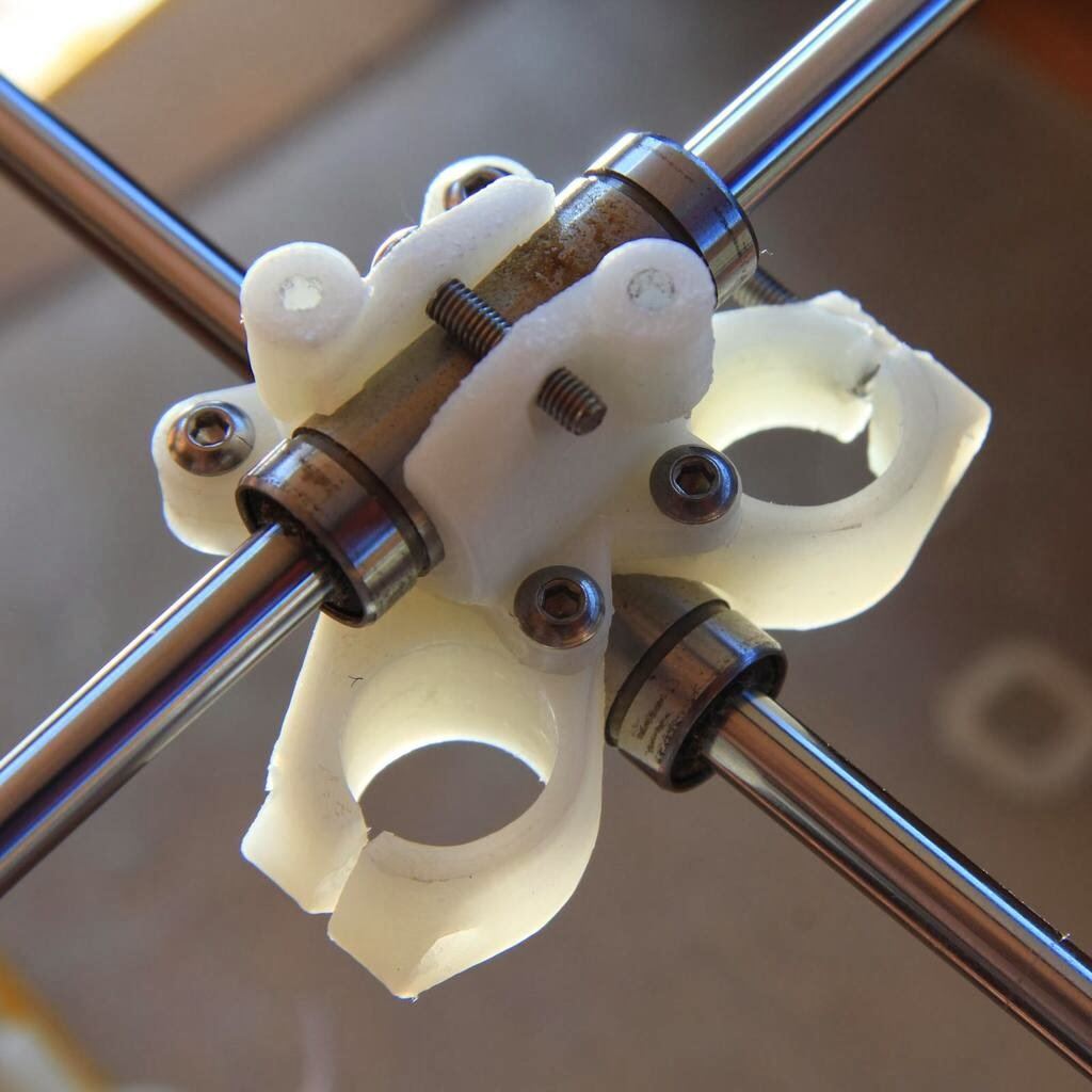
- Strong but can be tricky to print
- High strength
- High flexibility
- High durability
- Absorbs moisture (hygroscopic)
- Can warp
Tg 70 °C · 1.15 g/cm³ · 76 MPa · 2–4 GPa · 0.3–1.5% · ~40 €/kg
Flexible: TPU as example
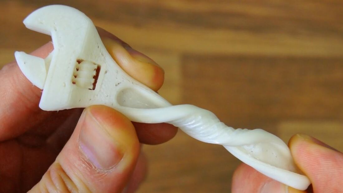
- Flexible and durable, but can be very hard to extrude
- Medium strength
- Very high flexibility
- Very high durability
Tg >150 °C · 1.1–1.2 g/cm³ · 28–54 MPa · modulus – · 0.4–1.4% · ~70 €/kg
Wood Composite · ~70 €/kg
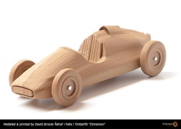
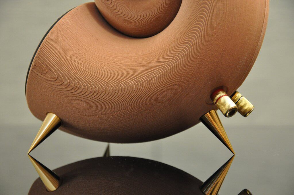
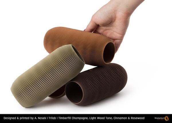
- Pine, birch, cedar, ebony, willow, bamboo, coconut, cork and olive
- ~30% wood particles
- Reduced flexibility and strength
- Can be sanded, stained and burnt
- Hard on the nozzle
Metal Composite · ~60 €/kg
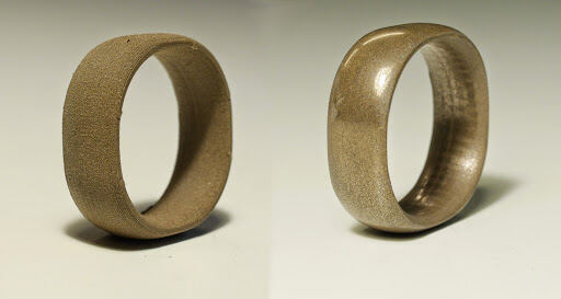
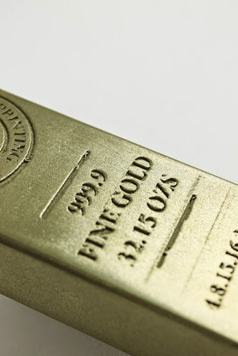
- Bronze, brass, copper, aluminium and stainless steel
- Very dense compared to other filaments
- Can be polished and weathered
- Rips through a brass nozzle
Conductive · ~850 €/kg (most expensive)
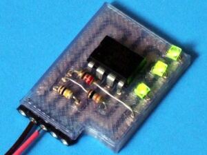
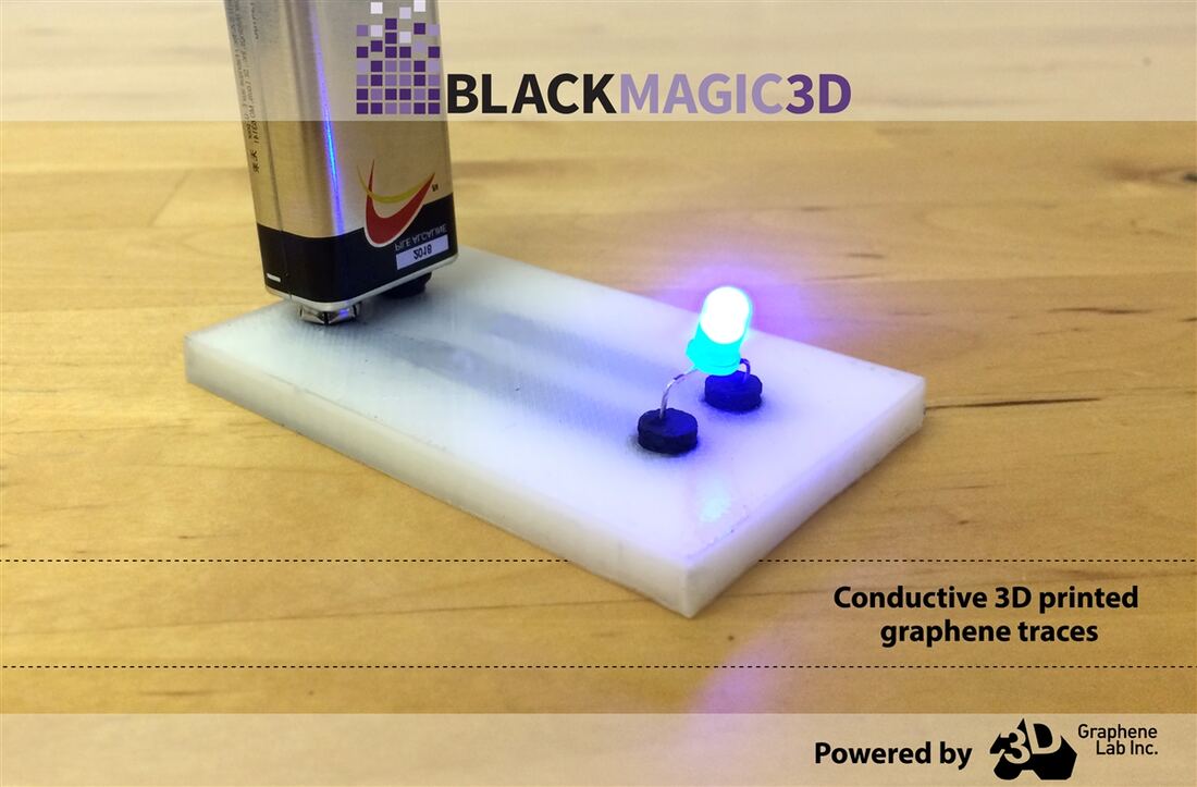
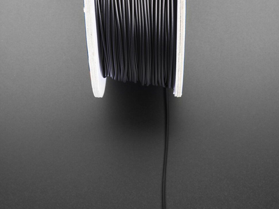
- Only suitable for low voltage
- High resistance
Glow-in-the-dark · ~30 €/kg
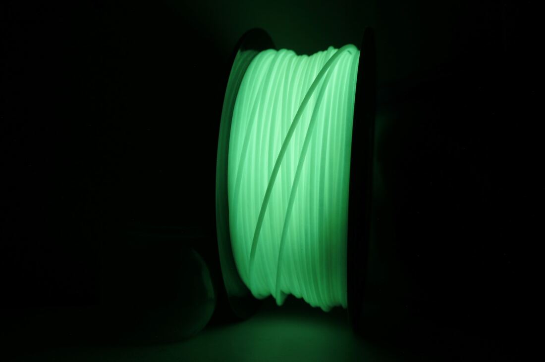
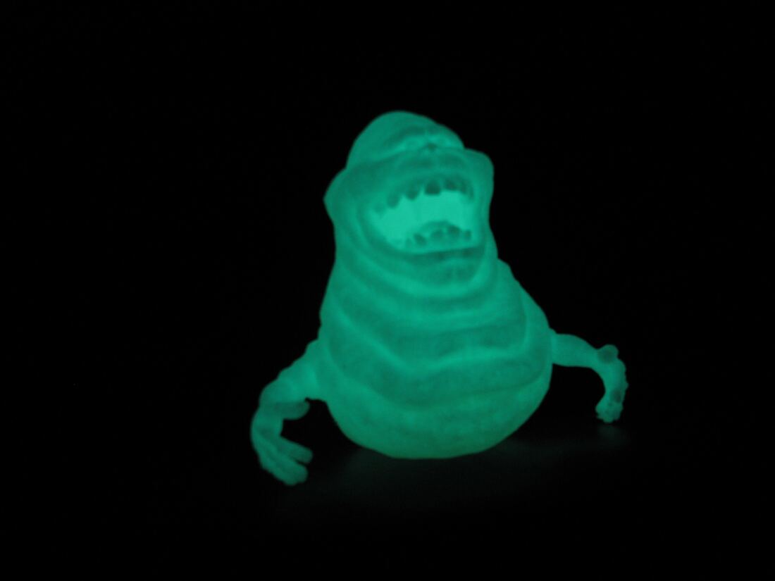
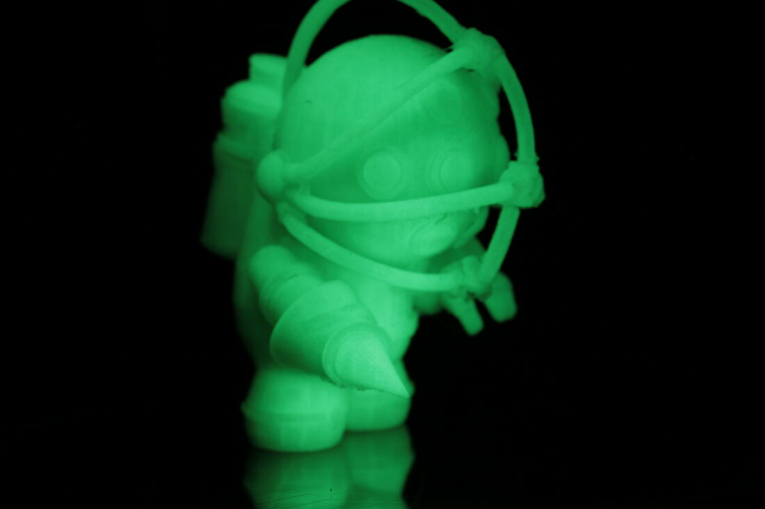
- Absorbs and later emits photons, so it only glows after being exposed to light
- Green is popular, but blue, red, pink, yellow and orange exist
Carbon Fiber · ~100–500 €/kg
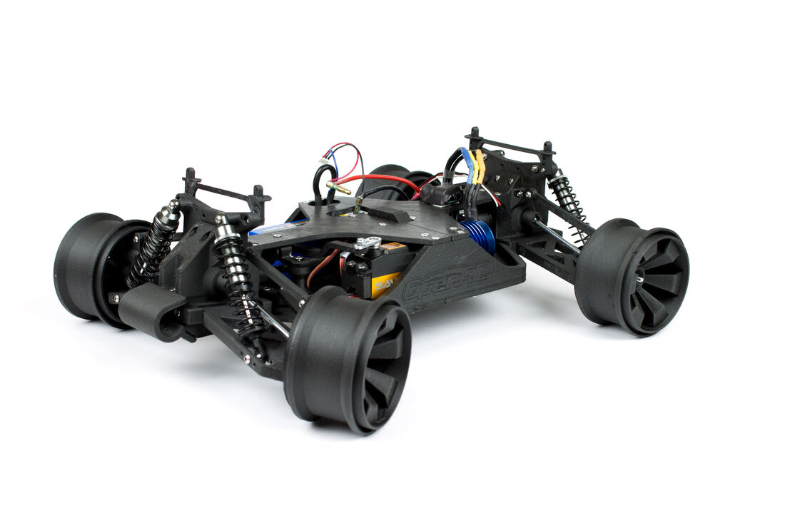
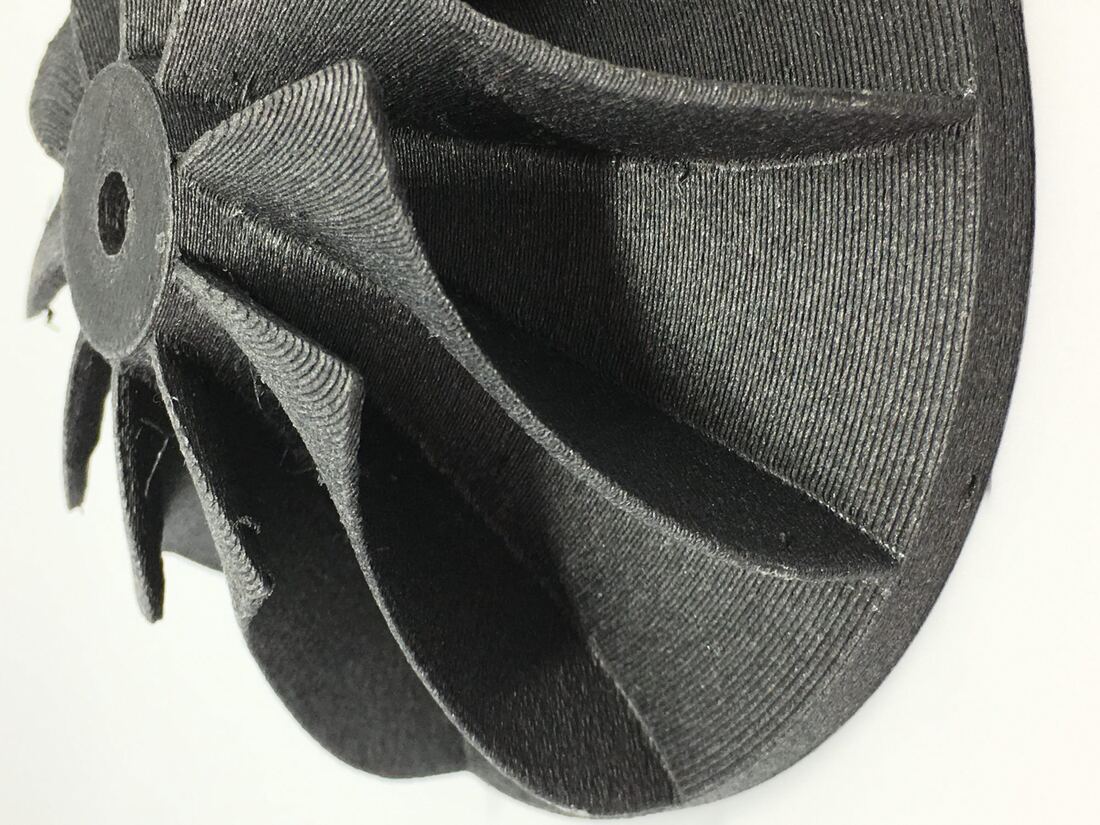
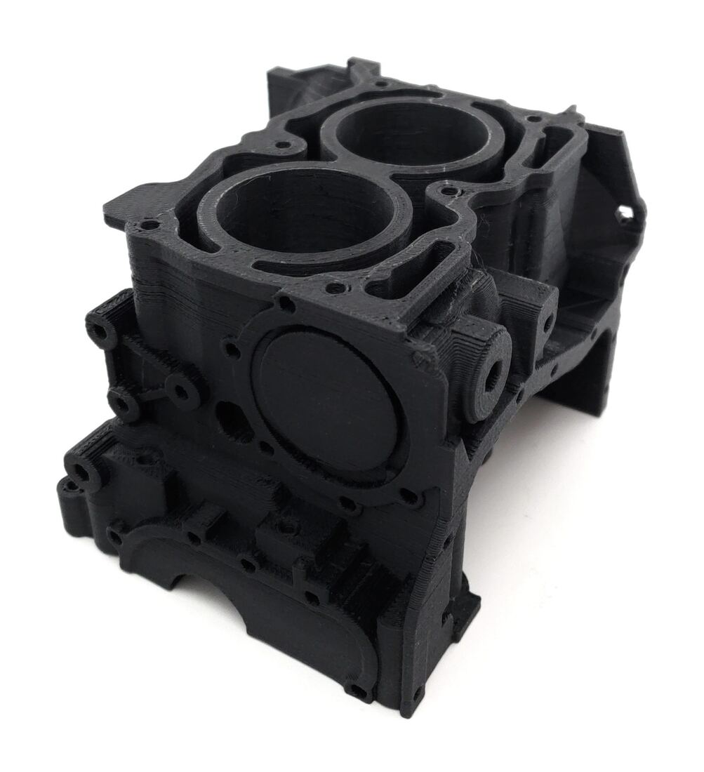
- Carbon fiber infused into bases such as PLA, ABS and PETG
- Makes stiff and rigid components
- Rips through a brass nozzle
Soluble · ~100 €/kg
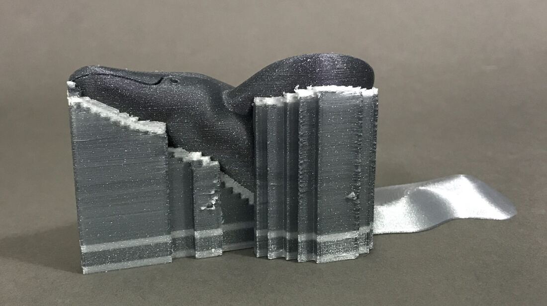
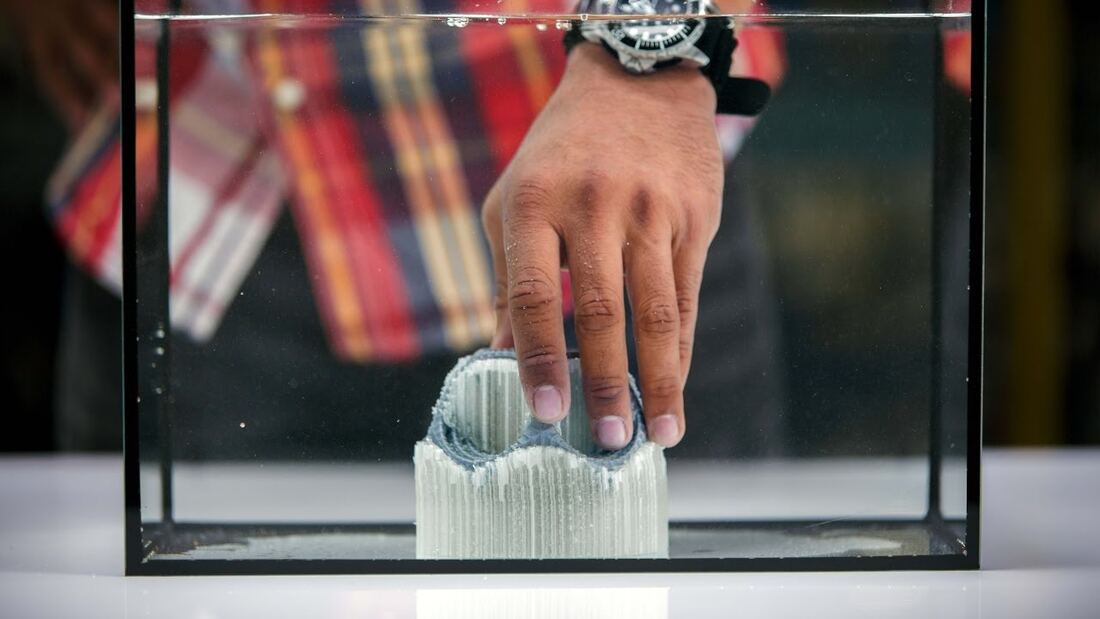
- Dissolves in limonene
- Can only be printed with ABS, because other materials are damaged by limonene
- Dissolves in water
- Can be printed with many materials (e.g. PLA + PVA supports on a dual extruder)
- Must be stored dry
9. The 7 AM technologies
Additive manufacturing technologies (3D Hubs infographic)
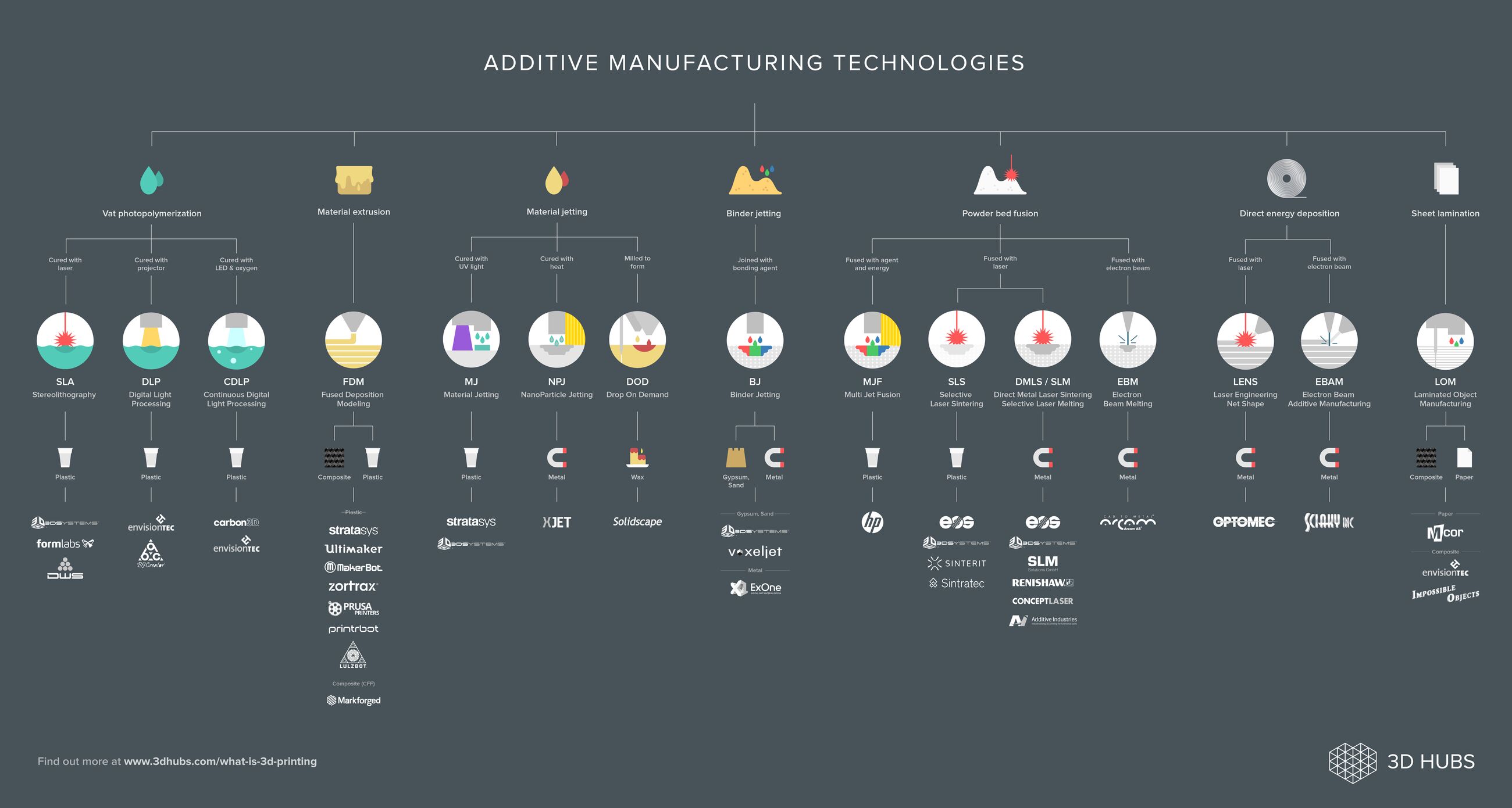
| Category | Process | How | Material | Companies |
|---|---|---|---|---|
| Vat photopolymerization | SLA (Stereolithography) | Cured with laser | Plastic | 3D Systems, Formlabs, DWS |
| DLP (Digital Light Processing) | Cured with projector | Plastic | EnvisionTEC, B9Creator | |
| CDLP (Continuous DLP) | Cured with LED & oxygen | Plastic | Carbon3D, EnvisionTEC | |
| Material extrusion | FDM (Fused Deposition Modeling) | Extruded through a nozzle | Plastic, Composite | Stratasys, Ultimaker, MakerBot, Zortrax, Prusa, Printrbot, LulzBot; composite (CFF): Markforged |
| Material jetting | MJ (Material Jetting) | Cured with UV light | Plastic | Stratasys, 3D Systems |
| NPJ (NanoParticle Jetting) | Cured with heat | Metal | XJet | |
| DOD (Drop On Demand) | Milled to form | Wax | Solidscape | |
| Binder jetting | BJ (Binder Jetting) | Joined with bonding agent | Gypsum, sand; metal | 3D Systems, voxeljet (sand); ExOne (metal) |
| Powder bed fusion | MJF (Multi Jet Fusion) | Fused with agent and energy | Plastic | HP |
| SLS (Selective Laser Sintering) | Fused with laser | Plastic | EOS, 3D Systems, Sinterit, Sintratec | |
| DMLS / SLM (Direct Metal Laser Sintering / Selective Laser Melting) | Fused with laser | Metal | EOS, 3D Systems, SLM Solutions, Renishaw, Concept Laser, Additive Industries | |
| EBM (Electron Beam Melting) | Fused with electron beam | Metal | Arcam | |
| Directed energy deposition | LENS (Laser Engineering Net Shape) | Fused with laser | Metal | Optomec |
| EBAM (Electron Beam Additive Manufacturing) | Fused with electron beam | Metal | Sciaky | |
| Sheet lamination | LOM (Laminated Object Manufacturing) | Sheets bonded and cut | Paper, Composite | Mcor (paper); EnvisionTEC, Impossible Objects (composite) |
Source: design-engineering.com additive manufacturing infographic / 3dhubs.com/what-is-3d-printing
1 · Vat Photopolymerization
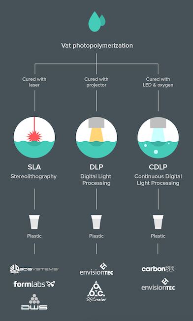
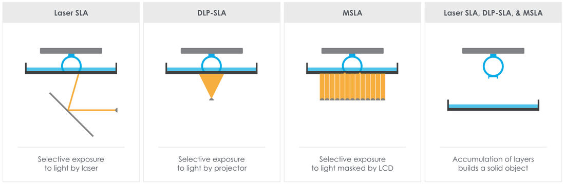
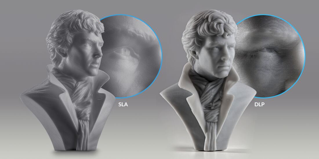
- Selectively solidifying layers of liquid resin, usually with ultraviolet light
- SLA = laser · DLP = projector · MDLP/MSLA = a mask that blocks the exposing light with black pixels
- High dimensional accuracy
- Fast printing
- Prints need supports
- Relatively low build volume (~120 × 70 × 200 mm)
Price: relatively inexpensive: 1,000–6,000 € per machine, ~80 € per litre.
2 · Material Jetting
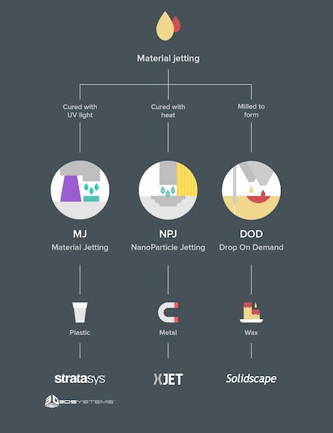
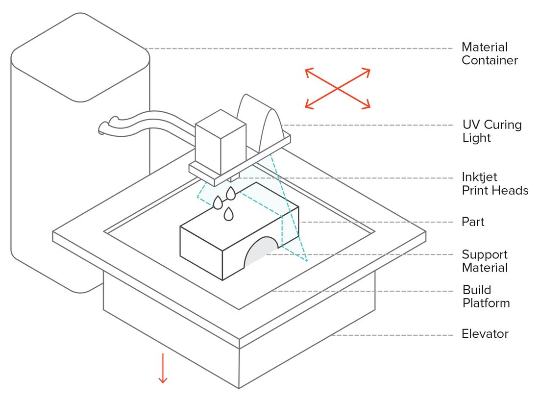

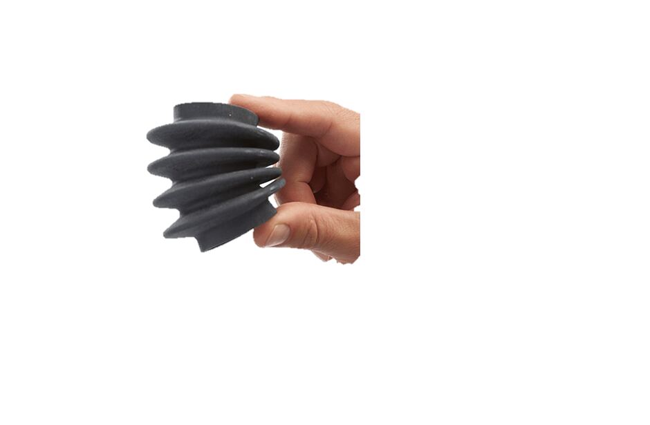
- Jetting = propelled violently in a usually narrow stream
- MJ: the print head jets droplets of material, which are then cured by photopolymerization
- NPJ: can print ceramics and metals
- DOD: wax-like materials, good for mould positives
- Enables multi-colour and multi-material prints
- Very high dimensional accuracy
- Finish comparable to injection moulding
- Mixed materials
- Prints need supports
- Very expensive
Price: expensive: 20,000–200,000 € per machine, 300–900 € per kg.
3 · Binder Jetting
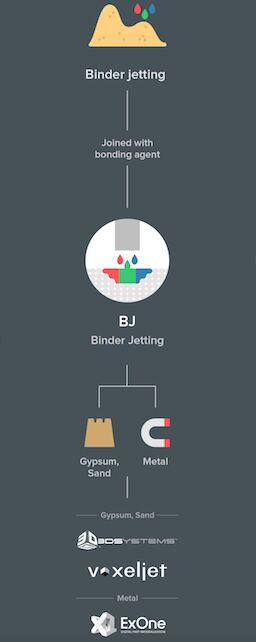
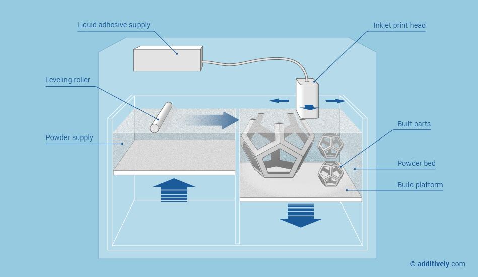
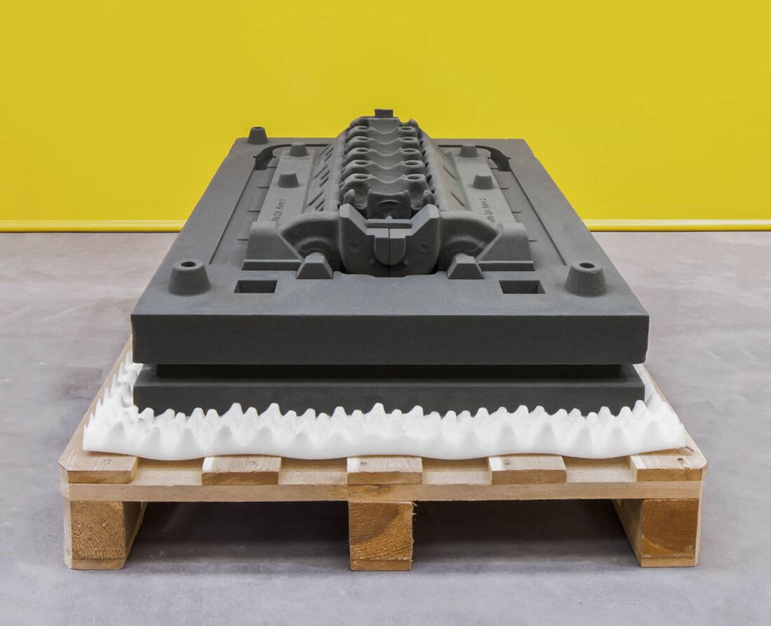
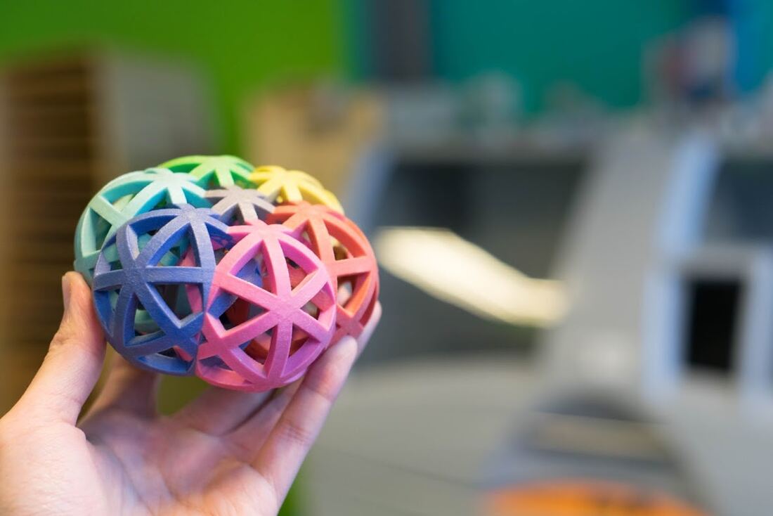
- A binding agent is any material that holds or draws other materials together into a cohesive whole: mechanically, chemically, by adhesion or by cohesion
- A layer of powder is bound with a binder jetted on like a printhead in a normal paper printer
- Can print metals, sands and ceramics
- Massive build volumes (4 × 2 × 1 m)
- High accuracy
- Fast
- No supports needed
- Limited mechanical properties
No price is given on the slide (the speaker notes literally say “MISSING”).
4 · Powder Bed Fusion
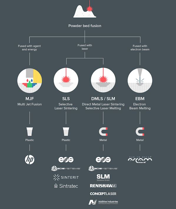
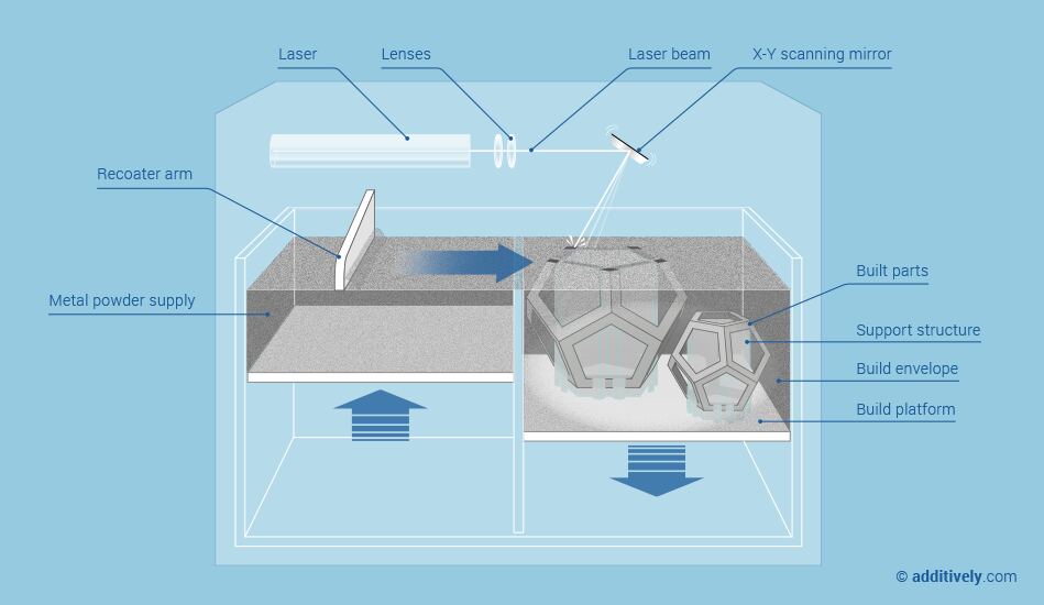
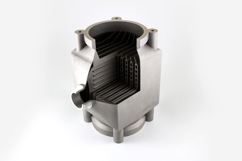
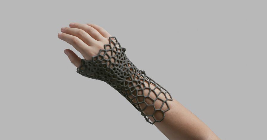
- MJF = multi-coloured plastics, cured with heat
- SLS = plastics with a laser
- SLM = metals with a laser
- EBM = metals with an electron beam
- Very high dimensional accuracy
- No supports
- Good structural abilities
- Very expensive
- Long print times
| Price | Machine | Material |
|---|---|---|
| SLS | 6,000–90,000 € | 120 €/kg |
| SLM | >250,000 € | 25–350 €/kg |
| EBM | >250,000 € | 300–400 €/kg |
5 · Directed Energy Deposition
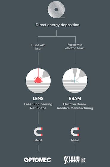
- Metal powder or wire is directed into the path of a laser or electron beam
- Similar to welding
- Used for repairs, near-net-shape manufacturing or hybrid manufacturing
- Functional-grade materials
- Controllable grain structure
- High deposition rates
- Low resolution
- No possible support material
Price: expensive.
6 · Sheet Lamination
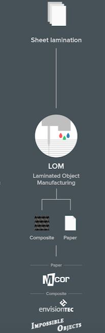
- Sheets of material are bonded together: metals with ultrasonic welding, paper with epoxy. The unbonded material is then cut or machined away.
- High speed
- Low cost
- Material handling
- Structural integrity relies on the adhesive used
- Limited materials
- Finish can be rough
Price: paper machines 10,000–40,000 €, material ≈ the price of A4 paper. Metal machines >250,000 €.
7 · Material Extrusion
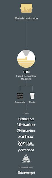
- FDM = Fused Deposition Modelling
- Simple machine mechanics
- Very inexpensive
- Fast
- Depends on calibration
- Rough finish
Price: 200–40,000 € per machine, 15–250 € per kg.
10. FDM anatomy & kinematics
FDM Anatomy
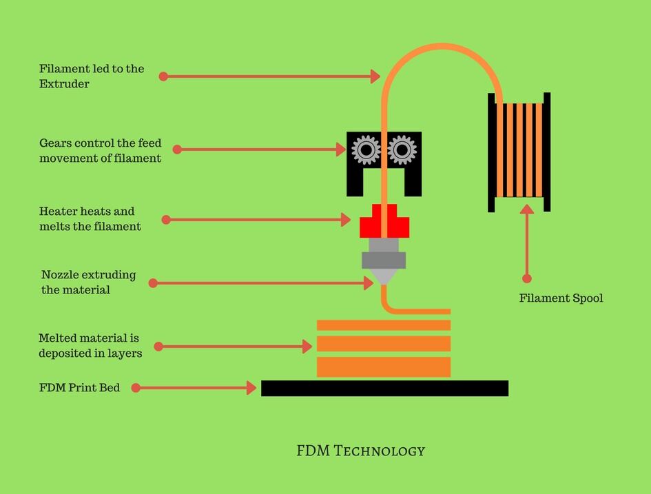
Kinematics
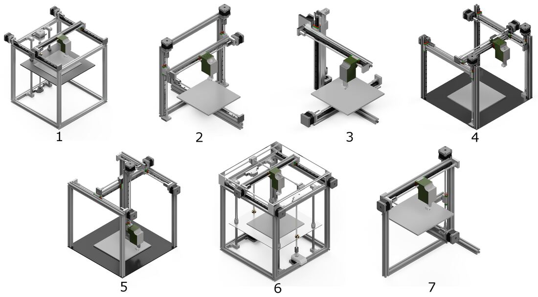
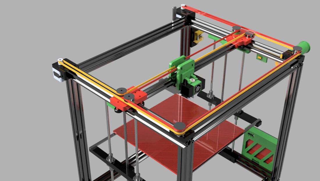
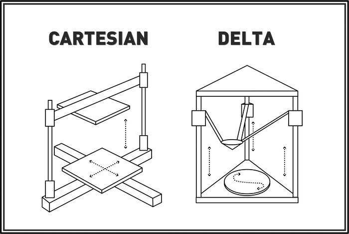
Speaker notes (slides 71–73): all 3D printers rely on calibration, especially FDM, both mechanically and in software. Again, especially FDM and SLA require a clean (or prepared) build plate for a good print. You must load the material, and this is done differently per technology: FDM with filament, SLA with resin, SLS with powder, etc.
11. Setup, part removal, post-processing
Printer Setup: Clean & Prepare → Load Material → Calibrate
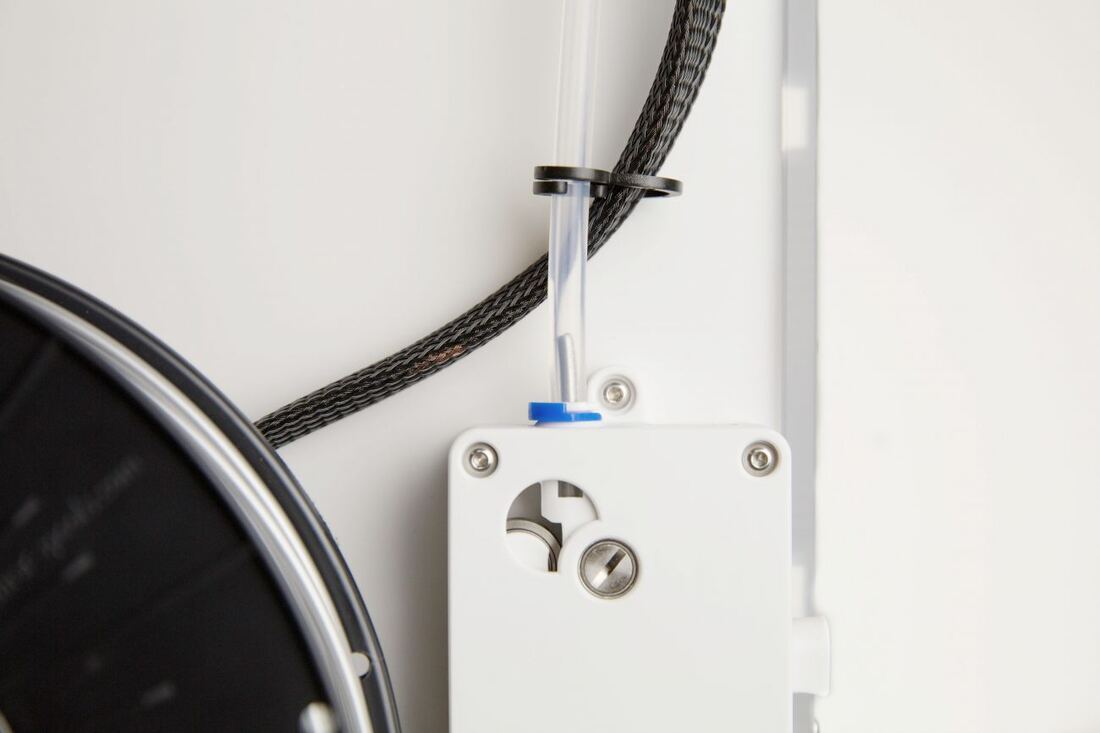
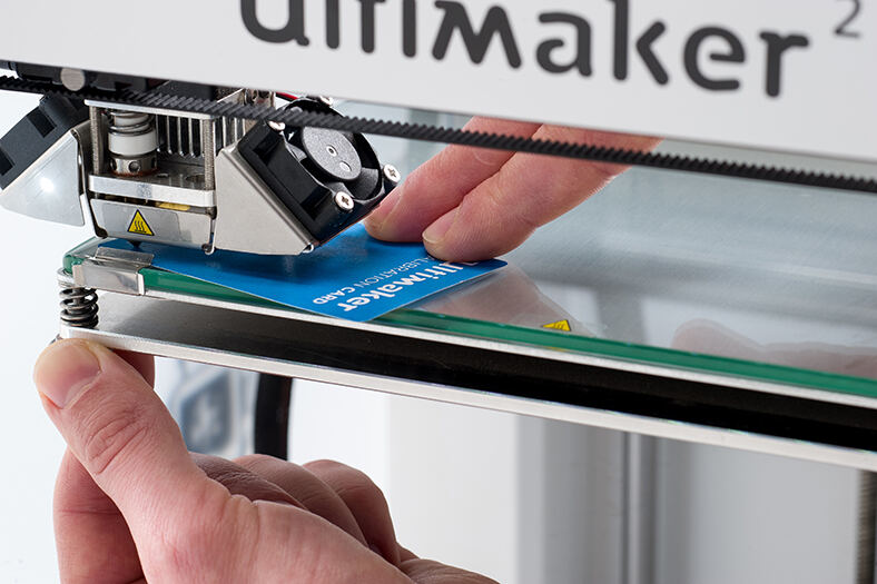
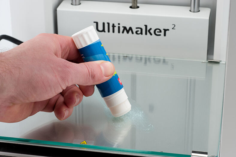
Part Removal
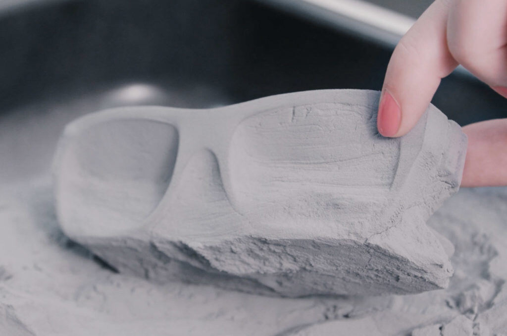
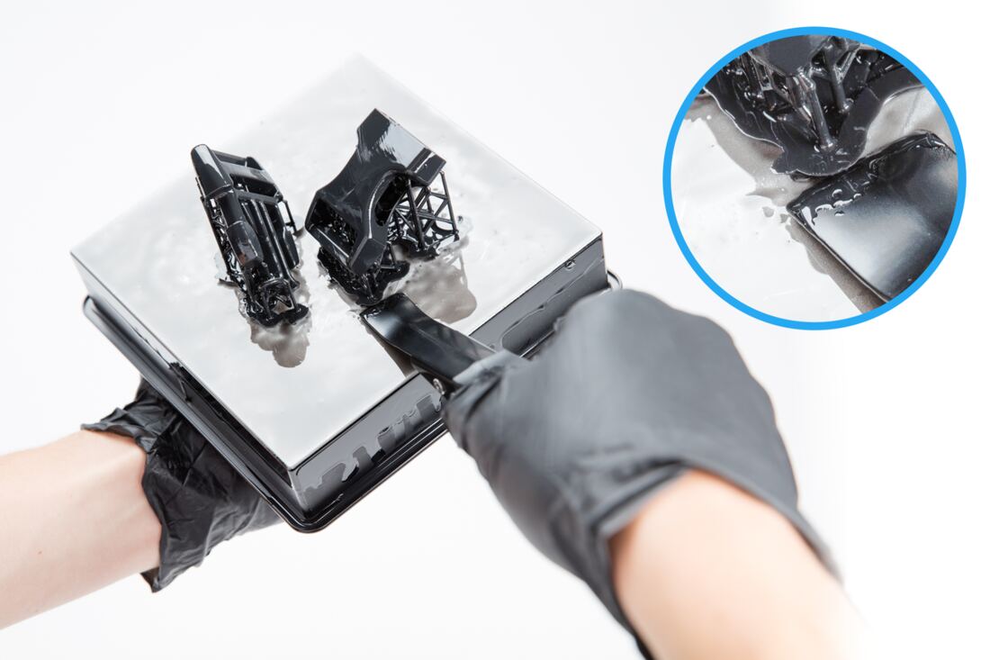
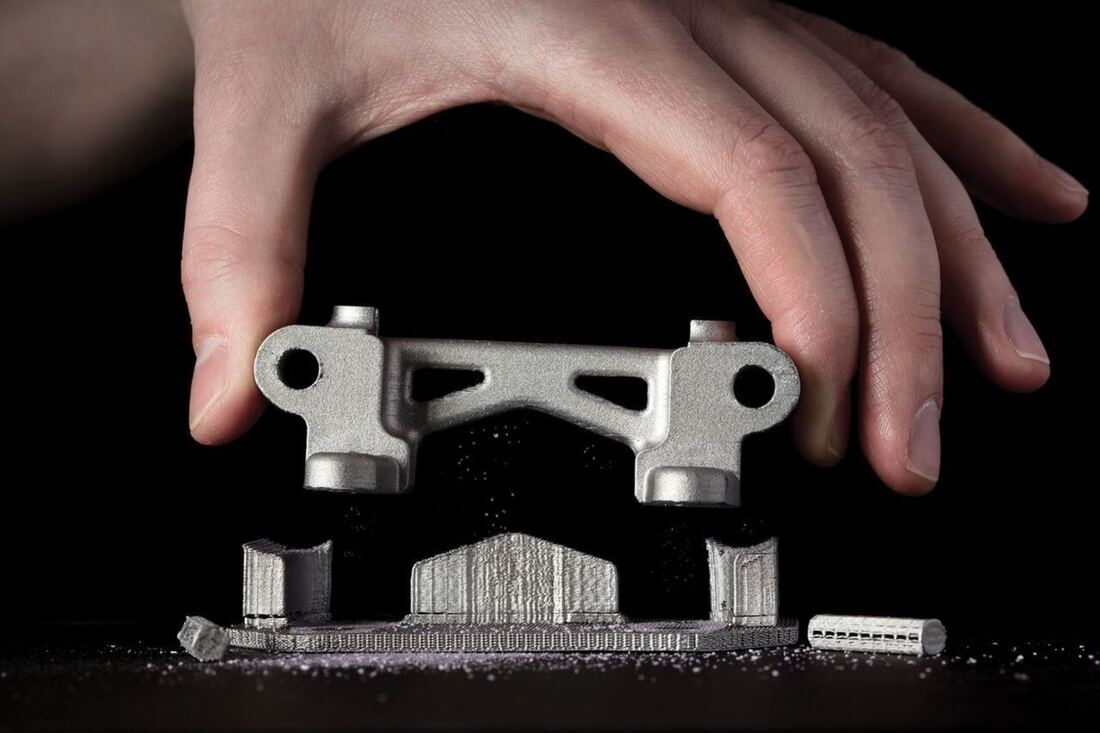
- FDM: you “break” parts off the build plate
- SLA: same, but with a bit more mess
- SLS and other powder-based technologies: dig out the part
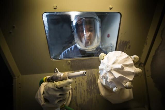
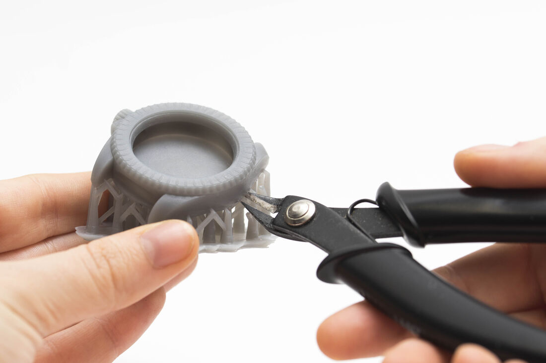
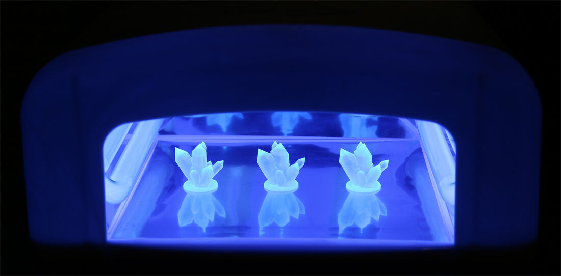
Post processing
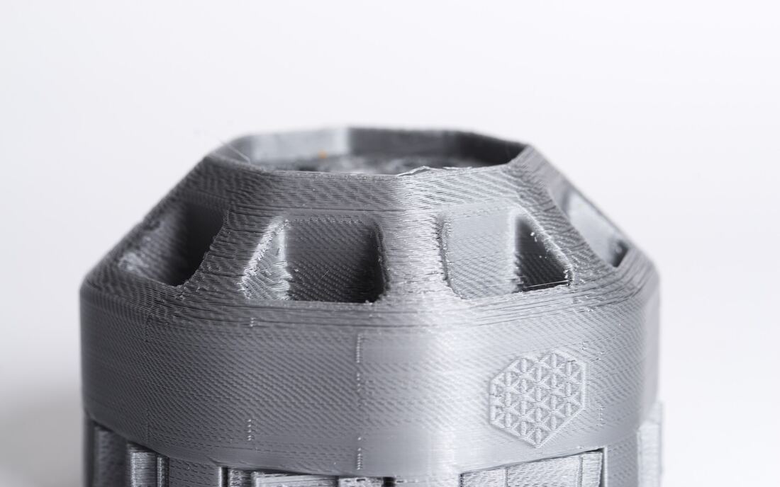
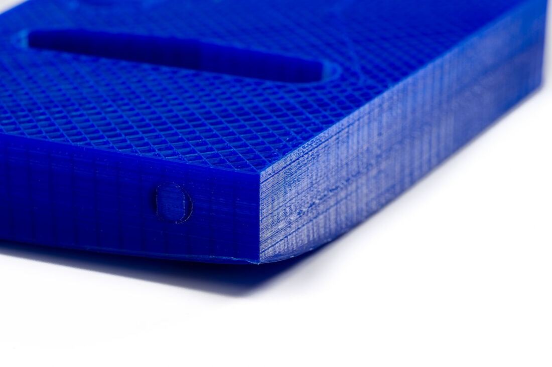
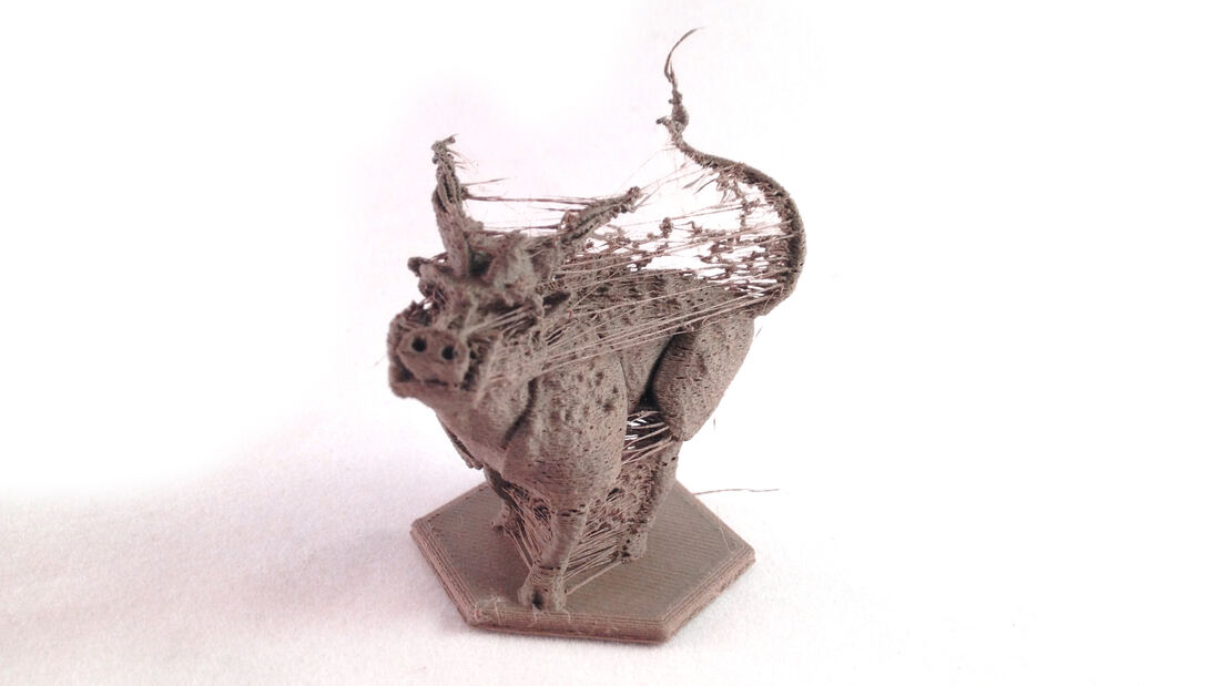
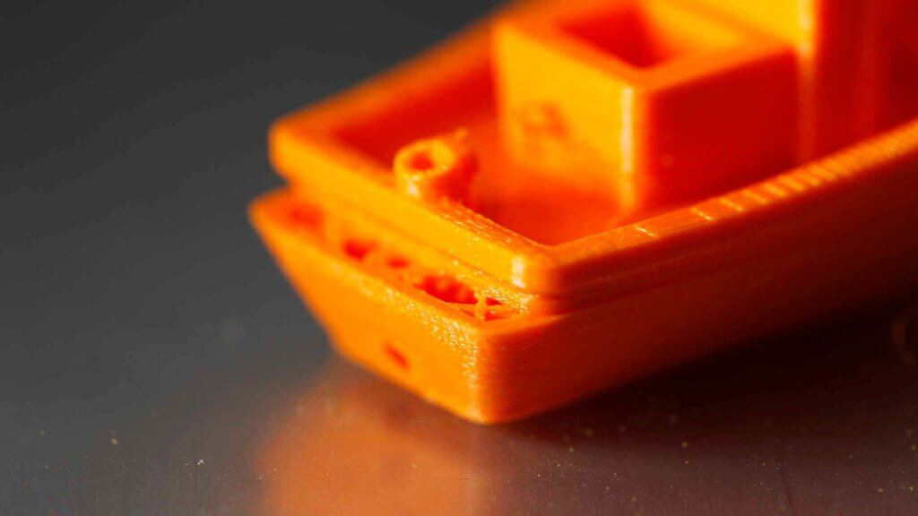
FDM Troubleshooting
Source: simplify3d.com/support/print-quality-troubleshooting/. Full guide below.
12. Simplify3D print quality troubleshooting guide
All 27 issues in the guide, each with every cause, fix and number from its detail page.
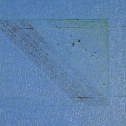
Not Extruding at Start of Print
Printer doesn't extrude at the beginning. Very common for new owners. Four possible causes:
- Extruder not primed: nozzles leak (ooze) when sitting idle hot, both while preheating and while cooling, leaving a void, so extrusion is delayed. Fix: prime before printing with a skirt (add more skirt outlines on the Additions tab if needed) or extrude manually with the Jog Controls.
- Nozzle starts too close to the bed: no room for plastic to exit. Symptom: nothing for the first 1–2 layers, normal from about the 3rd–4th as the bed lowers. Fix: Z-axis G-code offset (G-Code tab), e.g. +0.05 mm moves the nozzle further away. Increase in small steps.
- Filament stripped against the drive gear: shavings or a missing section of filament. See Grinding Filament.
- Extruder clogged: from debris in the nozzle, hot plastic sitting too long, or insufficient thermal cooling so the filament softens outside the melt zone. May need disassembly. Ask the manufacturer; the “E” string of a guitar fed into the nozzle tip works well.
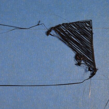
Not Sticking to the Bed
The first layer must bond strongly to the platform.
- Bed not level: one side too close, the other too far. Use the Bed Leveling Wizard (Tools menu).
- Nozzle too far from the bed: you want the filament slightly squished onto the plate. Z-axis G-code offset −0.05 mm = 0.05 mm closer. Small changes only (layers are ~0.2 mm).
- First layer too fast: use “First Layer Speed”, e.g. 50% = the first layer prints 50% slower.
- Temperature/cooling: plastic shrinks as it cools. An ABS part 100 mm wide printed at 230 °C and cooled to 30 °C shrinks almost 1.5 mm, but the bed doesn't, so the part separates. Heated bed (e.g. 110 °C for ABS): PLA 60–70 °C, ABS 100–120 °C. Disable the fan for the first layers (e.g. layer 1 at 0%, layer 5 at 100%). For ABS the fan is often off for the whole print. Keep drafts away.
- Build surface: BuildTak sticks well to PLA; heated borosilicate glass works for ABS. Keep it free of dust, grease and oils; clean with water or isopropyl alcohol. Tapes: PLA → blue painter’s tape; ABS → Kapton tape (polyimide film). Glue stick, hair spray.
- When all else fails: brims and rafts. A brim adds rings around the part (like a hat brim); a raft goes underneath. Both give more surface area for small parts.
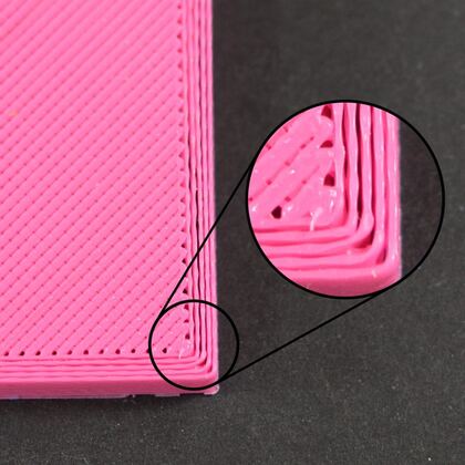
Under-Extrusion
The printer gives no feedback on how much plastic actually leaves the nozzle, so less can come out than the software expects. This causes gaps between adjacent extrusions.
- Test: print a 20 mm tall cube with at least 3 perimeters. At the top, gaps between the 3 perimeters = under-extruding.
- Incorrect filament diameter setting (Other tab). Measure with calipers. Common: 1.75 mm and 2.85 mm.
- Increase the extrusion multiplier (flow rate; Extruder tab, per extruder): 1.0 → 1.05 = 5% more. PLA ~0.9, ABS ~1.0. Increase 5% and reprint the cube.
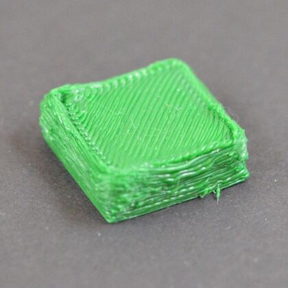
Over-Extrusion
Too much plastic, messy prints, ruined outer dimensions. Adjust the same settings as for under-extrusion in the opposite direction: decrease the extrusion multiplier.
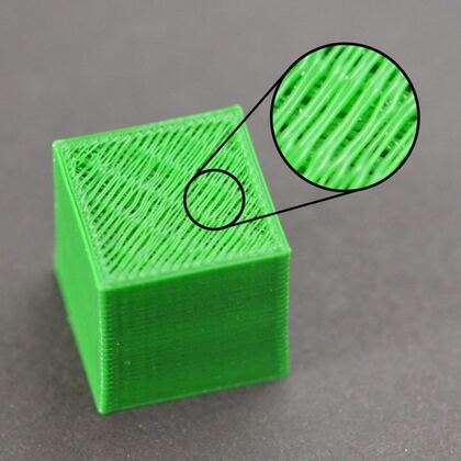
Gaps in Top Layers
Parts have a solid shell around a partly hollow interior (e.g. 30% infill = 30% plastic, the rest air). Example: 5 top and bottom solid layers on a cube.
- Not enough top solid layers: solid extrusions sag into the infill air pockets. Rule: the top solid section should be ≥0.5 mm: 0.25 mm layer → 2 layers; 0.1 mm → 5 layers. Try 3 → 5. Extra layers go inside the part dimensions.
- Infill percentage too low: 10% infill = 90% air, with big gaps to bridge. Try 30% → 50%.
- Under-extrusion: if the two above don't help.
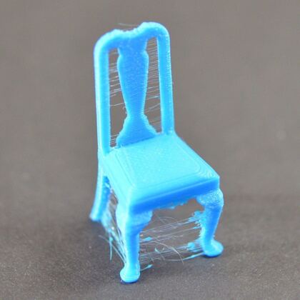
Stringing or Oozing
Also called whiskers or “hairy” prints. Plastic oozes out of the nozzle while it travels. Main countermeasure: retraction (filament pulled back into the nozzle before travel, pushed back in before printing resumes).
- Retraction distance (the most important setting): direct drive 0.5–2.0 mm; Bowden up to 15 mm. Try +1 mm.
- Retraction speed: too slow still oozes; too fast separates the filament from the hot plastic or grinds it. Sweet spot 1200–6000 mm/min (20–100 mm/s).
- Temperature too high: less viscous, leaks more easily. Lower by 5–10 °C (too low and it won't extrude).
- Long movements over open spaces: enable “Avoid crossing outline for travel movement”.
- Movement speed: a higher X/Y travel speed means less time to ooze.
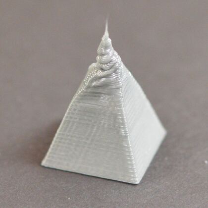
Overheating
Plastic exits at 190–310 °C. You need a balance between flowing freely and solidifying quickly. Example: the tip of a pyramid deforms.
- Insufficient cooling (most common): increase fan power, or add an aftermarket or handheld fan.
- Too high temperature: lower by 5–10 °C (not too far).
- Printing too fast: small layers don't get time to cool. Use speed overrides to slow down layers that take less than e.g. 15 s.
- When all else fails: print multiple parts at once, so the nozzle leaves each part and gives it time to cool.
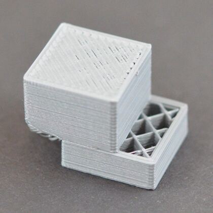
Layer Shifting
Most printers use open-loop control: no feedback about the actual toolhead position, so the printer can't detect or correct a shift (e.g. if you bump it).
- Toolhead moving too fast: the motors can't keep up and you hear clicking. Reduce the Default Printing Speed and X/Y Axis Movement Speed by 50%. Lower firmware acceleration.
- Mechanical: belts (rubber, fibre-reinforced) stretch over time. Too loose → the belt slips on the drive pulley; too tight → excess friction in the bearings. The belt should be somewhat tight, but not so tight the system can't rotate. A loose set screw (grub screw) on a motor pulley means the motor turns but the pulley doesn't.
- Electrical: not enough current to the motors, or overheating motor drivers stopping the motors until they cool.
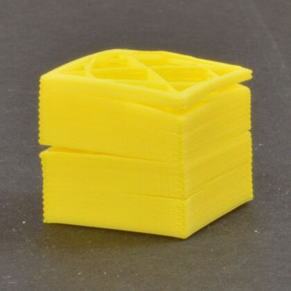
Layer Separation and Splitting
- Layer height too large: nozzles are 0.3–0.5 mm. Each new layer must be pressed onto the one below. Rule: layer height 20% smaller than the nozzle diameter (0.4 mm nozzle → max ~0.32 mm).
- Print temperature too low: warm plastic bonds better. ABS at 190 °C breaks apart easily; it needs 220–235 °C. Try +10 °C.
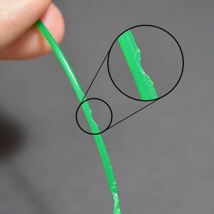
Grinding Filament
The drive gear (sharp teeth pressing the filament against a bearing) keeps spinning while the filament can't move, and grinds it away until nothing is left to grip (“stripped”). Signs: lots of small plastic shavings; the motor spins but the filament doesn't move.
- Aggressive retraction (too fast or too much): try 50% lower retraction speed.
- Increase extruder temperature by 5–10 °C: plastic always flows easier when hotter.
- Printing too fast: the motor spins slower if you print slower (e.g. 3600 mm/min = 60 mm/s → −50%).
- Check for a nozzle clog.
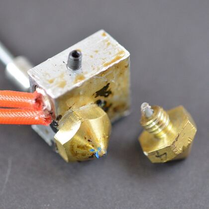
Clogged Extruder
Kilograms of plastic pass through a hole “only as big as a single grain of sand”. Clogs are usually something inside the nozzle blocking the flow.
- Manually push the filament: heat up, jog-extrude e.g. 10 mm while pushing lightly by hand.
- Reload the filament: retract it out (hot), cut away the melted/damaged part with scissors, reload.
- Clean out the nozzle: heat to 100 °C and pull the filament out manually (hopefully with the debris), or push a guitar E string back through the tip. Follow the manufacturer's instructions.
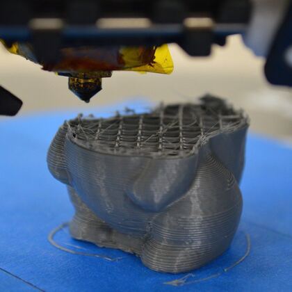
Stops Extruding Mid Print
- Out of filament: load a new spool.
- Filament stripped against the drive gear (printing too fast or extruding too much): motor spinning, filament not moving.
- Extruder clogged: check the filament is clean with no dust on the spool (dust builds up in the nozzle).
- Overheated extruder motor driver: drivers have a thermal cutoff. X and Y keep moving but the extruder doesn't. Turn the printer off, let the electronics cool, add a cooling fan.
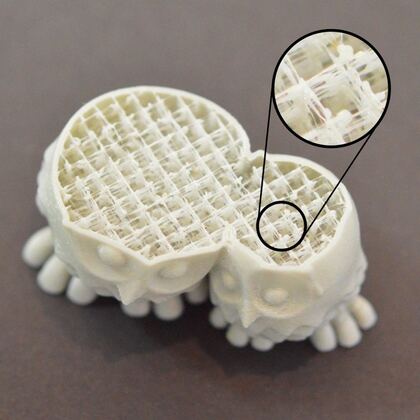
Weak Infill
Infill connects the outer shells and supports the upper surfaces.
- Try alternate infill patterns: Grid, Triangular, Solid Honeycomb are strong; Rectilinear, Fast Honeycomb trade strength for speed.
- Lower the print speed: infill is printed fastest, so the extruder can't keep up and under-extrudes. Try −50%.
- Increase infill extrusion width: e.g. 0.4 mm perimeters with 0.8 mm infill = 200%. Thicker, stronger infill walls. To keep the same %, lines are spaced further apart, so many users also raise the infill %.
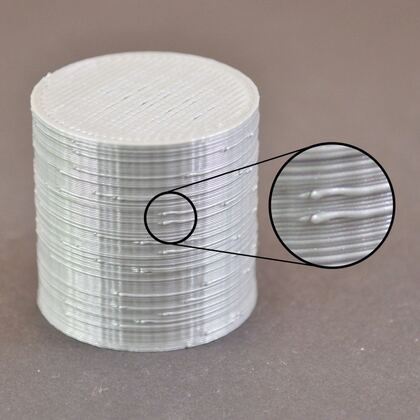
Blobs and Zits
Marks where the extruder starts/stops a perimeter. Watch whether the defect appears at the start or the end of a loop.
- At the start → priming too much. Use a negative Extra Restart Distance: e.g. retraction 1.0 mm with −0.2 mm → retracts 1.0 mm, primes only 0.8 mm.
- At the end → Coasting: turn off the extruder shortly before the end to relieve nozzle pressure. Typically 0.2–0.5 mm.
- Avoid unnecessary retractions (especially with Bowden extruders): “Only retract when crossing open spaces”, “Avoid crossing outline for travel movement”.
- Non-stationary retractions: enable “Wipe Nozzle” (wipe distance ~5 mm) plus “Perform retraction during wipe movement”, so the nozzle keeps moving while retracting and leaves no stationary blob.
- Choose the start-point location: random, or closest to a specific XY point, e.g. the back of a statue.
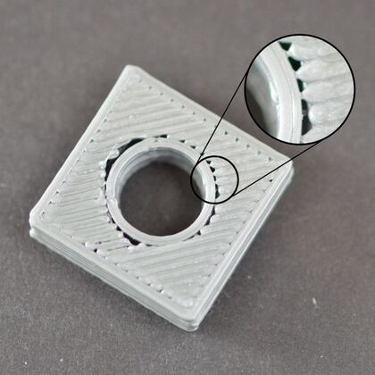
Gaps Between Infill and Outline
Perimeters trace the outline; infill uses a fast back-and-forth pattern. The two must bond.
- Not enough outline overlap (Infill tab; % of extrusion width): e.g. 20% → 30%.
- Printing too fast: the infill has no time to bond. E.g. 3600 mm/min (60 mm/s) → −50%, then increase gradually.
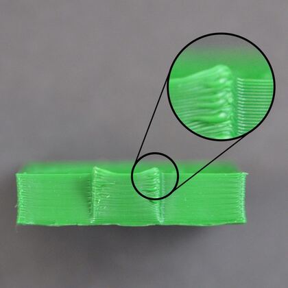
Curling or Rough Corners
Curling later in the print → overheating: the plastic doesn't cool fast enough and changes shape. Cool each layer rapidly. Curling at the very beginning → a bed adhesion problem.
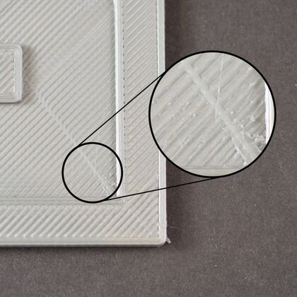
Scars on Top Surface
The nozzle drags across previously printed plastic while travelling.
- Extruding too much plastic: check over-extrusion first.
- Vertical lift (Z-hop): “Retraction Vertical Lift”, e.g. 0.5 mm, lifts the nozzle before travel. It only happens during a retraction. To lift on every move, disable “Only retract when crossing open spaces” and “Minimum travel for retraction”.
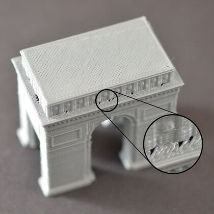
Gaps in Floor Corners
Weak foundation, most obvious where the size changes (e.g. a 20 mm cube on top of a 40 mm cube).
- Not enough perimeters: e.g. 2 → 4 (the wall thickness matters a lot because the interior is partly hollow).
- Not enough top solid layers: e.g. 2 → 4.
- Infill percentage too low: e.g. 20% → 40%.
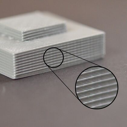
Lines on the Side of Print
One bad layer shows as a line or ridge. Often cyclical (e.g. once every 15 layers).
- Inconsistent extrusion, mostly poor filament quality: a 5% diameter variation can change the extrusion width by up to 0.05 mm.
- Temperature variation: a poorly tuned PID controller makes the temperature oscillate (sine-wave pattern). A tuned printer holds ±2 °C; if it varies more, recalibrate the PID.
- Mechanical: bed wobble or vibration; a Z-axis threaded rod not positioned properly (backlash, poor micro-stepping settings).
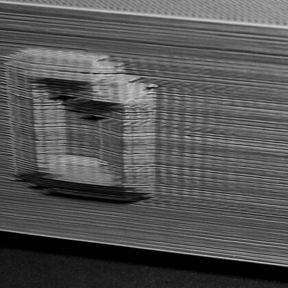
Vibrations and Ringing
A wavy pattern from vibrations/wobbling, seen at sudden direction changes such as sharp corners (inertia of the extruder), e.g. each face change of a 20 mm cube.
- Printing too fast (most common): lower the Default Printing Speed and X/Y Axis Movement Speed.
- Firmware acceleration: ramps speed up and down gradually. Decreasing it reduces ringing further.
- Mechanical issues: a loose screw or broken bracket.
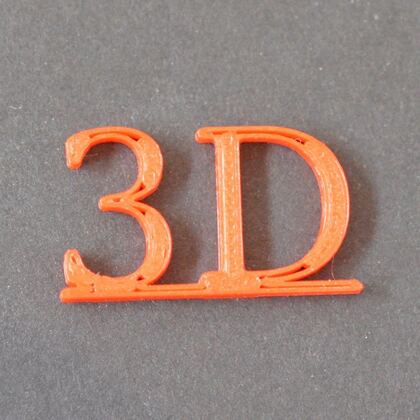
Gaps in Thin Walls
A fixed nozzle size causes trouble with walls only a few times wider than the nozzle, e.g. a 1.0 mm wall with a 0.4 mm extrusion width.
- Adjust the thin wall behaviour (Advanced tab, Internal Thin Wall Type): default “gap fill” (back-and-forth) or “Allow single extrusion fill” (one dynamic-width pass).
- Change the extrusion width to fit: e.g. a 1.0 mm wall → 0.5 mm extrusion. Best for consistent wall thicknesses.
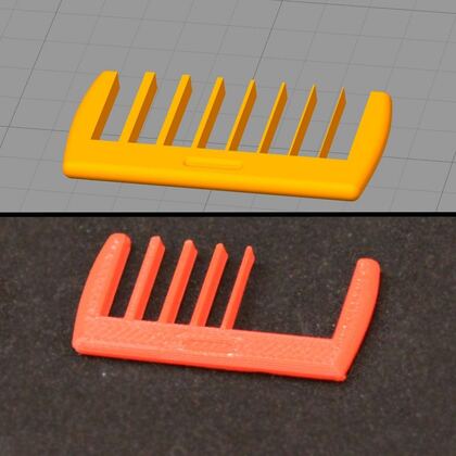
Small Features Not Printed
The nozzle size sets the XY resolution (popular sizes 0.4 or 0.5 mm). A 0.2 mm wall with a 0.4 mm nozzle may not even show in the preview.
- Enable single extrusion walls (External Thin Wall Type → “Allow single extrusion walls”).
- Redesign the part with features thicker than the nozzle (in CAD).
- Install a smaller nozzle, e.g. 0.3 mm (many users own a 0.3 and a 0.5).
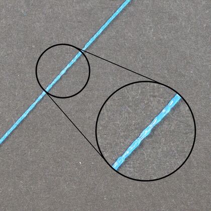
Inconsistent Extrusion
Identify by watching, e.g. a straight 20 mm line looks bumpy or varies in size.
- Filament stuck or tangled: the spool must rotate freely; check Bowden tube resistance (clean or lubricate).
- Clogged extruder: extrude manually and watch for an even flow.
- Very low layer height, e.g. 0.01 mm: no room for plastic to exit.
- Incorrect extrusion width: keep it within 100–150% of the nozzle diameter. A 0.2 mm width with a 0.4 mm nozzle gives inconsistent flow.
- Poor-quality filament: additives, inconsistent diameter, moisture (PLA absorbs it over time, hence the desiccant). Try a new high-quality spool.
- Mechanical: drive-gear tension too loose, so the teeth don't bite far enough.
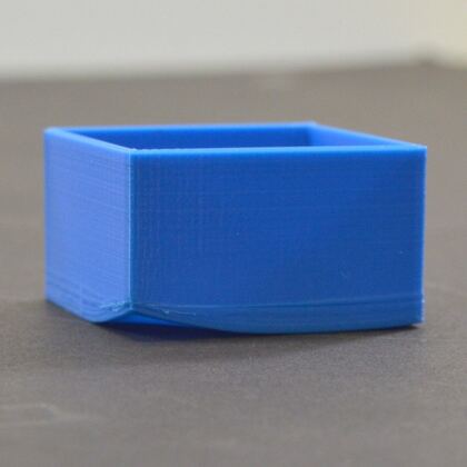
Warping
Large or long parts, especially high-temperature materials like ABS. The first layers stick, then the part curls and can separate. Cause: plastic shrinks as it cools. ABS printed at 230 °C shrinks almost 1.5% at room temperature, which can be several mm.
- Heated bed: ABS 100–120 °C.
- Disable fan cooling (common for ABS).
- Heated enclosure: keeps the upper layers warm on tall prints. Keep the doors closed.
- Brims and rafts: hold the edges down.
Poor Surface Above Supports
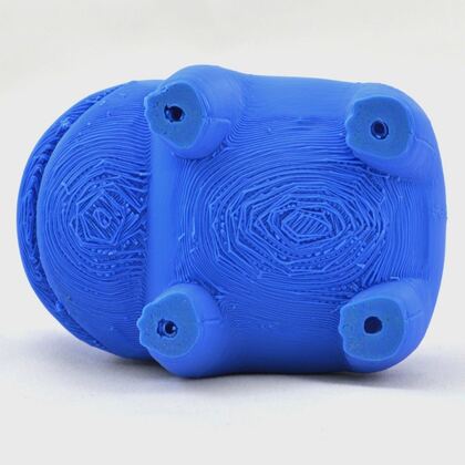
- Lower your layer height: 0.2 → 0.1 mm = twice as many layers and smaller overhang steps. Supports needed above 45° at 0.2 mm, ~60° at 0.1 mm. Less support needed and a smoother underside.
- Support infill percentage: commonly 20–40%. Or use dense support structures (dense only near the top).
- Upper vertical separation layers: empty layers between support and part. Same material: use at least 1–2; with 0 the supports bond and are hard to remove.
- Horizontal offset from the part: 0.2–0.4 mm.
- Second extruder: a different support material, e.g. PLA with water-dissolvable PVA. Then separation layers can be 0 and the offset ~0.1 mm.
Dimensional Accuracy
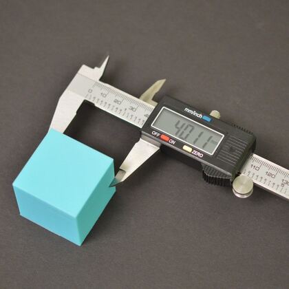
Factors: under/over-extrusion, thermal contraction, filament quality, first-layer nozzle alignment.
- First layer impact: a nozzle too high or low affects the next 10–20 layers (e.g. a 0.2 mm layer with the nozzle only 0.1 mm from the bed = oversized bottom). Print 50–100 layers and measure only the top ~20.
- Extrusion multiplier: too low = gaps, holes on top, parts too small. Too high = bulging tops, parts too large.
- Constant error (e.g. always 0.1 mm too big, whether 20 or 100 mm wide) → Horizontal size compensation −0.1 mm (Other tab; shrinks X and Y).
- Increasing error (0.1 mm too small at 20 mm, 0.5 mm at 100 mm) → thermal contraction (common for ABS). Shrinkage = 0.1/20 = 0.5% → scale 100.5%. Can be automated with an Import Action.
Poor Bridging
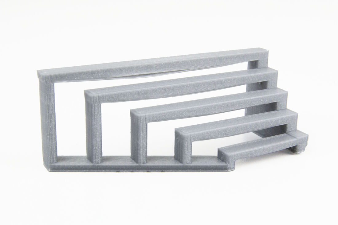
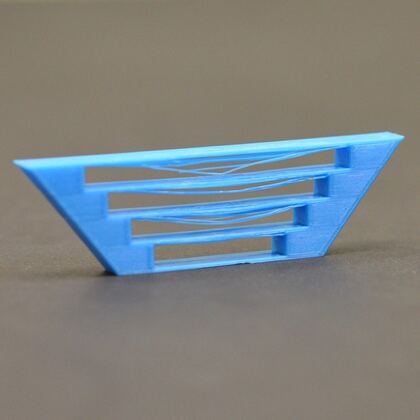
Bridging = extruding between two points with no support below. Short bridges need no supports (saving material and time); large ones may. Symptoms: sagging, drooping, gaps.
- Verify bridging settings are used: preview in “Feature Type” colouring, where bridges are yellow. If not, check the “Unsupported area threshold” (the region must be larger) and “Apply bridging settings to perimeters”.
- Bridging infill angle: calculated automatically so the infill runs along the bridge (e.g. pillars on X → infill along X). Or use a fixed bridging angle.
- Optimise settings: bridging extrusion multiplier 100% or more. Bridging speed multiplier: experiment (some printers do better slow, others fast). Bridging fan speed override high to cool quickly.
- Use supports for longer bridges.